A few nights ago, on May 1st, 2019, I achieved the biggest and most significant milestone yet at Applied Ion Systems since I first started these efforts over a year ago – the first full system qualification test and high vacuum pumpdown! This test so far has been the single most important, high stakes, and significant test done yet for these efforts. It was the culmination of a year’s worth of intensive engineering, planning, design, research, calculation, simulation, system integration, and build. Not only for the work I have done here at Applied Ion Systems, but this project has represented the most intensive engineering effort I have ever worked on, and is a highly interdisciplinary merging of many engineering fields, including vacuum, mechanical, thermals, fluids, electrical, control, instrumentation, and software.
Unexpectedly, the system performed exceptionally, and in fact performed exactly to engineering specification. Even more impressively, the system performance was on par with prior calculations and simulations. During the prior year, part of the engineering design was a steady-state thermal analysis of the diffusion pump and baffle, as well as a Molflow simulation of ultimate vacuum levels for different levels of conditioning. Before implementing the final CAD model and vacuum simulations, preliminary hand calculations were performed. For reference, the calculations, thermal analysis, and vacuum analysis can be found on the following pages:
- MICRO PROPULSION TESTING CHAMBER DESIGN SPECIFICATIONS
- STEADY-STATE THERMAL ANALYSIS OF A HIGH VACUUM DIFFUSION PUMP AND BAFFLE ASSEMBLY
- MOLFLOW SIMULATION OF A MICRO PROPULSION TESTING CHAMBER
As a reference of measured calculated and simulated performance vs. measured performance, the results are as follows:
- COOLING SYSTEM: Simulated steady-state average baffle temp with 15C ambient and cooling with full diffusion pump load was 21C. Actual measured baffle temperature with 15-16C ambient conditions and peltier chiller module activated was 22C.
- HIGH VACUUM SYSTEM: Hand calculated final pressure for ideal outgassing numbers for very short pumping times was 3.8 x 10^-6 Torr. Simulated pressure with Molflow+ for ideal outgassing numbers for very short pumping times was 3 x 10^-6 Torr. Actual ultimate measured pressure was 6 x 10^-6 Torr. Outgassing rates are higher than ideal since all fresh materials and new oil was used, in addition to several more viton o-rings used than initial calculations and simulation.
- ROUGHING SYSTEM: Estimated maximum foreline pressure goal was set at 3.0 x 10^-2 Torr under full diffusion pump load during pumpdown. Actual measured foreline pressure was stable at 2.8 x 10^-2 Torr.
Data for the run was captured, displayed, and logged with the custom MegunoLink interface I had previously worked on. Originally, the system was supposed to offer both full control and monitoring – however, in order to simplify setup, the program was simplified for monitoring only. At the moment, cooling system temperature, ambient temperature, ambient humidity, and chamber pressures can be recorded. During the test, 2 out of the 6 cooling system thermocouple channels were out of commission. However, plenty of excellent cooling data was captured, from the primary points of interest. For future tests, cooling system flow rates and foreline pressure will be logged. I will also need to troubleshoot the two thermocouple channels.
The first plot below shows the data captured on the HPT-100 vacuum transducer, which allows me to measure from atmosphere down to 10^-10 Torr. Communication utilizes a Pfeiffer protocol through RS-485, which I have connected to the Arduino from the gauge through a UART to RS-485 converter.
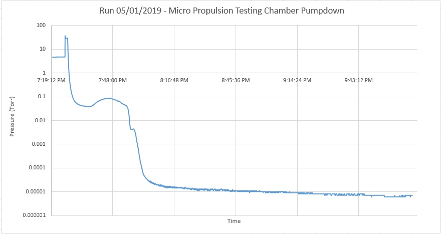
As can be seen from the graph, the pressure in the chamber reflects the different stages of pumping operation when using the diffusion pump. The chamber was initially still at around 5 Torr from a previous roughing check. The roughing line valve was opened after the pump was turned on, resulting in the brief spike in pressure, rapidly dropping down to a bit less than 30 millitorr. At this point, the diffusion pump power was switched on. Since it was a bit colder that day, warm up of the boiler and oil took longer than expected. Once the pump got heated up however, the fresh oil began to outgas in the low vacuum, making a rise in chamber pressure up to 90 millitorr, in which the diffusion pump started pumping. The peak of this hump can be seen at around 7:48 PM. After some time of pumping, the pressure slowly dropped. As pressure decreased, pumping efficiency of the pump increased, and a critical point is reached where pumping speed rises. From here, the pressure rapidly dropped to 10^-4 Torr after only a few minutes, where pressure began to slowly taper off and drop down into the 10^-5 Torr range. From initial cold-start of turning on the diffusion pump to reaching the 10^-5 Torr range took about 30 minutes. For the next couple of hours, the pressure continued to drop. After a total run time of about 3 hours, the final pressure read at 6 x 10^-6 Torr. For PPT testing, 10^-5 Torr is sufficient, with a goal ultimate pressure in 10^-6 Torr range. Both of these numbers were met without any issue. Outgassing was still present, and could be easily seen from small bumps in the pumpdown curve when zoomed in. Since the pressure seemed to be continually dripping, there appears to be no major leaks in the system at this level, and with additional pumping and baking, it is expected to bottom out at the low 10^-6 Torr range. This has successfully validated the entire design of the roughing and high vacuum systems, including all of the o-ring, baffle, and adapter plate interfaces.
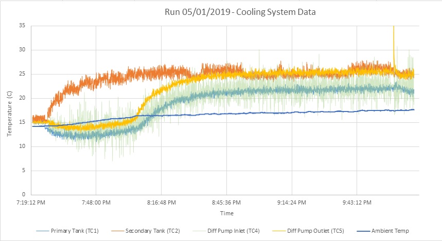
The next graph shows data collected from the cooling system. The cooling system was turned on initially to give the chiller some time to lower the temperature while roughing was performed. Main tank temperatures slowly dropped, and the secondary tank for the peltier hot side cooling rose, showing that the chiller was indeed operational. Over Once the diffusion pump was turned on, the cooling system was subjected to the full thermal load of the pump. After reaching the nominal operating temperature, temperature in the cooling loop rose. With the chiller and heat exchangers on, against the full diffusion pump heat load, a steady-state temperature of 22C was achieved. The peltier hot-sides were maintained at 25C, and ambient temperature slightly rose from 14C to 17C as the room warmed up a bit from the equipment running. Of interest was also the heat rise noted as a result from the diffusion pump. From the cooling inlet to cooling outlet, with a flow rate of about 1 gpm, and a cooling mixture of 30% inhibited propylene glycol, a temperature rise of 3C was observed.
This represented another big success with the system, and verified that the closed-loop, peltier-chilled system could indeed maintain desired cooling levels of the diffusion pump loop. This is particularly important, since diffusion pump and baffle cooling are critical for proper operation. The cooling system was rebuilt and upgraded several times, and represented a very challenging endeavor to build a compact, thermoelectric cooled system. It was a bit of a gamble, since peltier based coolers are particularly challenging to work with, and the system has never been tested under full heat load until this test. It also shows that with proper planning and design, a peltier chiller module can be used to help with a diffusion pump cooling system.
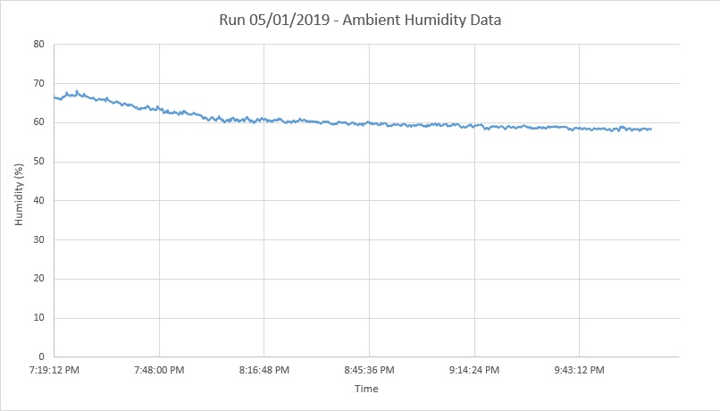
Finally, humidity data is shown for reference. As the room warmed up, humidity dropped from about 67% to 59% during the pumpdown phase. This is good additional information to know, to further qualify pumpdown and look at system performance at varying levels of humidity for different runs.
One important thing that I will do for every test is log and save all of the data for every test run and pumpdown. Now that I can record system temperature, environmental temperature and humidity, and pumpdown curves, I can compare collected data from each run to qualify my system performance based on operational and environmental factors. This can be a very powerful tool for benchmarking and troubleshooting down the road, and allows me to understand every operational parameter and variation in my system to a very low level.
With the completion of this first monumental milestone, the Integrated Test Stand has been fully verified to operating at the design specifications for all subsystems. This validates a year’s worth of engineering design effort, and shows successful deployment of the system. With high vacuum levels achieved to the desired target pressure, actual experiments can begin. The first experiments that will be performed will be testing and qualification of the pulsed plasma thrusters developed here at Applied Ion Systems. The first thruster, the AIS-uPPT1 micro pulsed plasma thruster, is already mounted in the chamber, with high voltage and trigger supplies already set and ready. If ignition is successful, then lifetime testing of the thruster will begin. After, the second thruster, the AIS-gPPT1 gridded pulsed plasma thruster, will begin its initial cycle of testing.
With the operation of this system and the pulsed plasma thrusters, I hope to bring an unprecedented level of data and results to the open-source and maker community for both vacuum system performance, as well as high vacuum qualification of advanced electric propulsion for space applications.