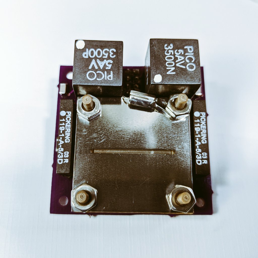
In my previous post, I reviewed the third ignition test of the AIS-ILIS1 ionic liquid electrospray thruster. In this post, I review the details of the next test that happened, occurring the next day on 08/17/2020.
During the prior test, while evidence of multi-site emission was observed in post-test video analysis, the tolerances of the 0.5 mm wide aperture extractor slit with flared edges resulted in too tight spacing for manual alignment, causing immediate shorting and failure of the thruster upon turn-on. As a result, it was decided to evaluate the operation of the new V6 electronics board with a very wide slit to prevent rapid failure. The original 1 mm wide standard slit, which was used during the first ignition test of the ILIS1, was selected. However, during the first test, the emitter-extractor spacing was found to be too high at 0.5 mm. This current test utilizes the most recently modified and adjusted housing, setting the extractor-emitter spacing to 0 mm.
After the new extractor plate was polished and cleaned, the ILIS1 was taken out of the vacuum chamber, which was still held to roughing levels from the prior test earlier that day. Any charring or burned fuel residue on the porous glass emitter was carefully wiped away as much as possible. The thruster was re-assembled, with the emitter and extractor centered and aligned by sight. Due to the much larger aperture of 1 mm wide, alignment was significantly easier to achieve. The thruster was then mounted to the Faraday cup test stand, and the assembly was mounted into the micro propulsion testing chamber, centered in full view in the 6” conflat viewport, and wired up for thruster power and control.

Since only the extractor was changed between the prior test and this test, and the thruster being held in vacuum until the extractor swap, fueling and bakeout was not necessary to prepare for this current test. The chamber was evacuated to a pressure of 2×10^-5 Torr before starting up the thruster. In order the better prep the thruster for long duration operation, and slowly bring it up to full power, a conditioning sequence was first employed, in which the thruster would be operated in manual monopolar mode. During this conditioning phase, thruster polarity would be set to one output continuously, and the voltage would be manually and very slowly increased, keeping the voltage set in various steps for several minutes, before switching polarities, and repeating.
The thruster controls were turned on, and the thruster set to manual monopolar mode operation starting with the +HV. Power was slowly increased over a period of several minutes. The thruster voltage was continuously increased in small increments up to 5kV, in which no visible emission was observed. Since the thruster electronics were operating stably otherwise, the oscilloscope monitor was turned on, and the Faraday cup output was connected. Across the Faraday cup output is a 100k shunt resistor to ground, giving a reading of 10uA/V. A small value capacitor was also placed in parallel with the shunt resistor to reduce high frequency AC noise. The thruster was turned off, and watching the monitor, turned on and voltage manually raised slowly again. Despite no visible ion emission from the thruster, the oscilloscope readout indicated emission was indeed occurring!
After running the thruster in manual mode and switching between both positive and negative polarities, I decided to switch operation to automatic bipolar mode. The thruster was operated at 10 seconds per polarity, with a 2 second transition between polarities. The control program was uploaded to the controller, and again the thruster was started at low power, slowly raising the emitter voltage in steps. Positive and negative swings on the oscilloscope were observed, corresponding to the thruster polarity. At a voltage of +/-4kV, oscilloscope readouts were at +9mv and -4mV, corresponding to a measured beam current of +90nA and -40nA. The test was run for a period of about an hour, with stable emission observed at the prior indicated levels, and no arcing or shorting failures occurring during the duration of the test. Below is a video of the Faraday cup readout on the oscilloscope during testing.
During the test, video was recorded of thruster operation. While emission could not be physically seen during the test, it was later discovered after analyzing the video that emission was in fact present at one corner of the emitter.
Assuming purely ionic emission, we can calculate some rough initial performance estimates. For thrust, let’s assume PIR with 50% monomers and 50% dimers. Averaging this for both monomer/dimer emission with EMI/BF4 beams, max theoretical thrust is 73nN. Taking into consideration non-ideal real-world operational losses due to thruster inefficiencies, assuming 30% for reasonable losses, this gives an average thrust of 51nN. For ISP, assuming the same PIR mode of operation with 50% monomers and 50% dimers, at +/-4kV this gives a max average theoretical ISP of ~7300s. However, in literature it has been shown that there is about a 50% discrepancy between measured ISP and theoretical max ISP, most likely due to polydispersive losses in the beam, which factored in gives a more realistic ISP of 3650s. Although these numbers are very rough estimates based on operating mode assumptions, beam current readings, and emitter operating voltages, this can give a reasonable first approximation of performance currently expected from the thruster during this test.
Once again, the test was unsuccessful in achieving full multi-site emission across the ridge. However, the test marked a major advance in beamline diagnostic capabilities, marking the first time ever that I recorded output beam from a thruster. The new V6 electronics were also operated stably over an extended period of time without issues, showing that the design was
In my next post, I will be reviewing the fifth ignition test of the ILIS1, where some exciting stuff started to happen!
The full official test report for the fourth ignition test of the AIS-ILIS1 can be found below:
