On August 16th 2020, I ran the third ignition test of the AIS-ILIS1 ionic liquid electrospray thruster. This post will recap the details of the test.
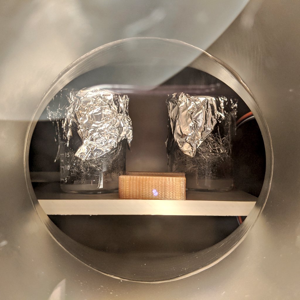
The first phase of the test, degassing and baking the ionic liquid fuel and thruster housing went very smoothly without issues. The fueling and baking procedure for the ionic liquid fuel and Ultem 1010 housing remained the same as the prior test. Both the porous glass emitter and reservoir were placed in their own separate Pyrex beaker, just large enough to fit the 25mm diameter discs. The beakers were then filled with ionic liquid just barely over each of the discs. The rest of each beaker was filled with 316 stainless steel wool at the top to act as a baffle to prevent excessive splattering as well as keeping the discs from bouncing around. The tops of the beakers were then covered tightly with aluminum foil to further prevent any droplet spray into the chamber during pump-down and degassing.
The filled beakers, Ultem printed housing, and vacuum thermocouple, were mounted on a scrap PEEK baseplate that rested inside the chamber, to prevent direct heating from the chamber during bakeout. The system was pre-pumped with the roughing pump the night prior and sealed to facilitate faster pumpdown during the fueling phase of the test.
The internal temperature was maintained between 65-80C for a duration of 2.5 hours, at which the chamber was kept at a vacuum level of around 2 x 10^-5 Torr. After the baking and degassing cycle was complete, and the system shut down and allowed to cool, preparations were made for the second phase of the test.
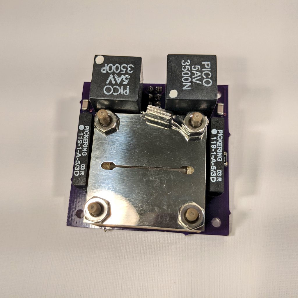
After fueling was completed, final assembly and system preparations were made for the next phase of ignition testing. The thruster components were cleaned, and with the fully loaded emitter and reservoir, assembled into the final thruster. For this test, I selected to use the new 0.5mm wide aperture enhanced extractor electrode, as well as the newly modified housing to help mitigate liquid creep failures. Assembly was real tough this time. Because I was using an even thinner slit than last time, which was 0.75mm wide, and the emitter-extractor distances is so small, manual alignment was incredibly difficult, and I didn’t have the tools to do it properly yet. There was honestly a high probability of failure going into this.
The thruster was then mounted to the Faraday cup test stand, which is used to collect and measure beam current, verifying operation of the thruster, and giving initial estimates of thrust and ISP performance. The stand also allows for simplified placement and mounting within the chamber, as well as alignment of the thruster to the Faraday cup input.
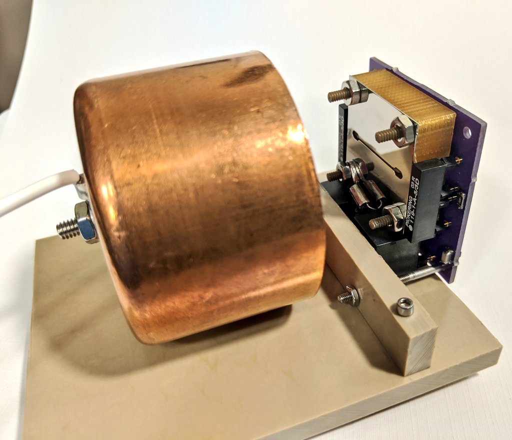
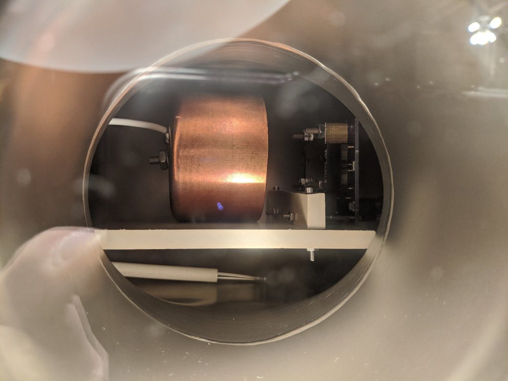
The test stand was then mounted into the micro propulsion testing chamber, centered in full view in the 6” conflat viewport, and wired up for thruster power and control.
To recap the changes from last time, the following changes were made for this test:
- modified housing
- modified extractor
- modified board w/ surge protection resistors
- smaller pore reservoir to choke flow and decrease droplet emission to achieve PIR
- new conditioning procedures to work towards stable emission
The chamber was evacuated to a pressure of 2×10^-5 Torr before starting up the thruster. Pumpdown was very fast due to the prior vacuum system conditioning and pumping during the prior days as well as the bakeout phase. In order the better prep the thruster for long duration operation, and slowly bring it up to full power, a new conditioning sequence was adopted, in which the thruster would be operated in monopolar mode, very slowly increasing emitter voltage, before switching polarities, and repeating.
The thruster controls were turned on, and the thruster set to manual monopolar mode operation starting with the +HV. Power was slowly increased, when the thruster emitter flashed briefly, immediately arcing and failed, showing signs of continuous shorting. The test was quickly terminated, and the vacuum system shut down to inspect the thruster.
During the test, video was captured of the thruster during operation. Although the test lasted for only a few seconds before the thruster arced and failed, there was enough video captured to determine key points of fault. Below is a video of the failure sequence slowed down to 0.125x speed to better see what is going on.
It was discovered that during the initial emission flash, the thruster did in fact exhibit multi-site emission along the central region of the emitter. In addition, no arcing or emission was observed at the emitter edges. This was the first time that evidence of multi-site emission along the central length of the ridge was captured for the ILIS1.
After testing the thruster was removed from the chamber for disassembly and inspection. It was immediately observed that there were several burn marks at various points along the ridge emitter, indicating the areas the thruster shorted at between the emitter and extractor. However, no burning, arcing, or emission was observed at the edges, confirming the new extractor design functioned as expected in reducing field enhancement at the corners, and forcing high field strength along the central region of the ridge.
Unfortunately, the test was unsuccessful, however it gave a small glimmer of hope that multi-site emission may actually be possible with some additional modifications, and that I was heading in the right direction with the new enhanced extractor design. In my next post, I will review the fourth ignition test of the ILIS1, which took place immediately after this test.
The full official test report of the test can be found below: