In my previous post, I reviewed the fourth ignition test of the AIS-ILIS1 ionic liquid electrospray thruster. In this post, I review the details of the next test for the thruster, occurring the next day on 08/18/2020. This is the test were things really started to heat up for the ILIS1!
During the prior test, beam current and low-level ion emission was observed for the first time using the Faraday cup test stand, with the standard 1mm wide aperture slit extractor. In order to increase field enhancement at the porous glass ridge emitter, and increase thruster output, a narrower 0.75mm wide slit extractor was selected. This aperture was used during the second ignition test of the ILIS1 with the V5 thruster board and original thruster housing. Due to the thruster housing design, the thruster failed after a short period of operation due to liquid creep along the surface, bridging between the emitter and extractor, in which the high voltage conducted through and charred the fuel. In addition, issues with the V5 board caused failure of the –HV supply, only allowing the +HV supply to operate. The new housing design aimed to mitigate these liquid creep issues, and the new V6 board was designed to allow for more stable operation.
After the new extractor plate was polished and cleaned, the ILIS1 was taken out of the vacuum chamber, which was still held to roughing levels from the prior test earlier that day. No charring or damage to the emitter was observed from the prior test. The thruster was re-assembled, with the emitter and extractor centered and aligned by sight. Due to the 0.75mm wide aperture size, alignment was relatively easy to achieve visually, by holding the thruster up to the light and looking across the thruster from either side with the HV relays removed, as well as visual alignment to center the ridge from the top.
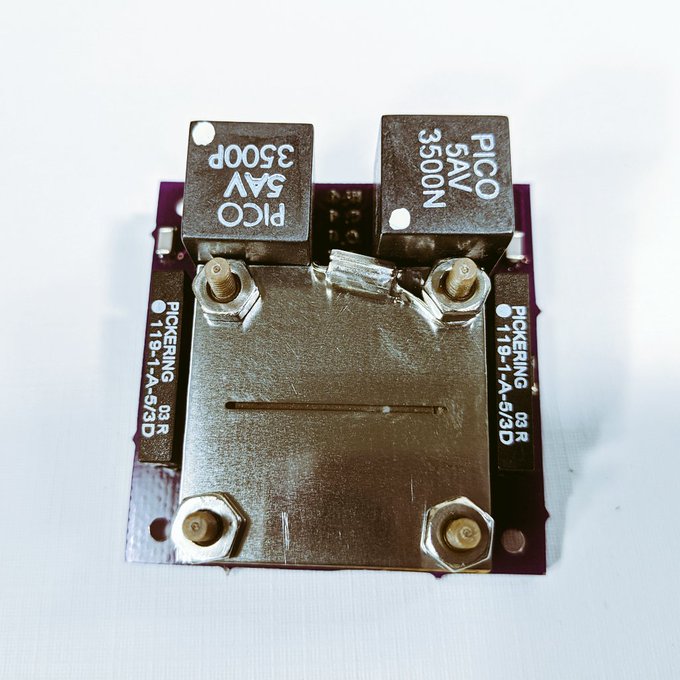
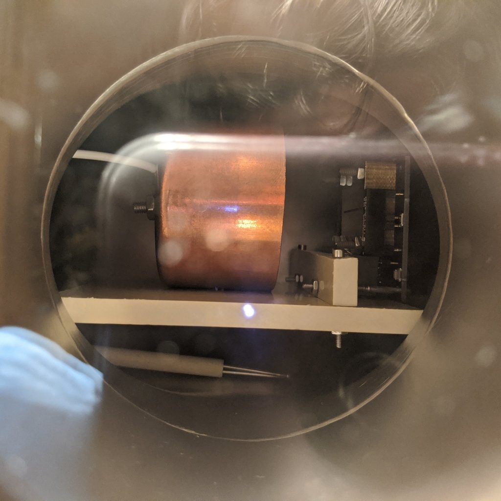
The thruster was then mounted to the Faraday cup test stand, and the assembly was mounted into the micro propulsion testing chamber, centered in full view in the 6” conflat viewport, and wired up for thruster power and control.
Since only the extractor was changed between the prior test and this test, and the thruster being held in vacuum until the extractor swap, fueling and bakeout was not necessary to prepare for this test. The chamber was evacuated to a pressure of 2×10^-5 Torr before starting up the thruster. The thruster was first started at minimum power in manual monopolar mode, first with +HV for several minutes, then switching to –HV to make sure the circuit was operational as expected and to establish minimum output. A very faint, barely visible glow was confirmed at the corner during this warm-up phase, indicating emission had started. Off to a good start, an immediate improvement from the prior two tests!
After the warm up phase, the thruster control was set to automatic bipolar mode with the same timing sequence as the prior test, at 10 seconds per polarity, with a 2 second interval between polarity transitions. Input voltage to the thruster was slowly increased until the output readout indicated the thruster was operating at +/-4kV. Readout from the oscilloscope looking at the Faraday cup with 100k shunt resistance was at +/-20mV, indicating +/-200nA of beam current! Already a massive increase in emission current!
After about 10 minutes operating stably like this, the time per polarity was increased to 30 seconds, and the voltage slowly raised to +/-4.5kV. At this point, beam readout was still at +/-200nA of current. After 30 minutes of continuous operation, beam current began to rise to +/-500nA, with thruster voltage at +/-4.6kV.
After 40 minutes total run time of operation at +/-500nA, thruster power was further increased until the thruster reached a peak beam current of +/-2uA! Voltage peaked at +/-4.8kV, however during operation settled back down to +/-4.7kV. This was the most output beam current I had seen yet! The plume was very noticeable and bright at this point.
The thruster was operated in this higher emission mode for a period of 10 minutes before the thruster arced between the emitter and extractor, leading to shorting failure. Overall, the thruster was operated stably for a period of 50 minutes total during the ignition test, the longest period of operation yet at noticeably higher beam current!
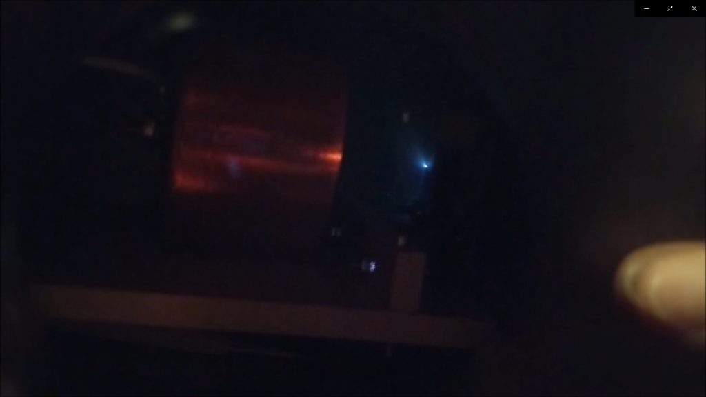
Video of both the thruster operation as well as the beam readout were taken during the test. This first set of videos shows the thruster operating in nominal output mode.
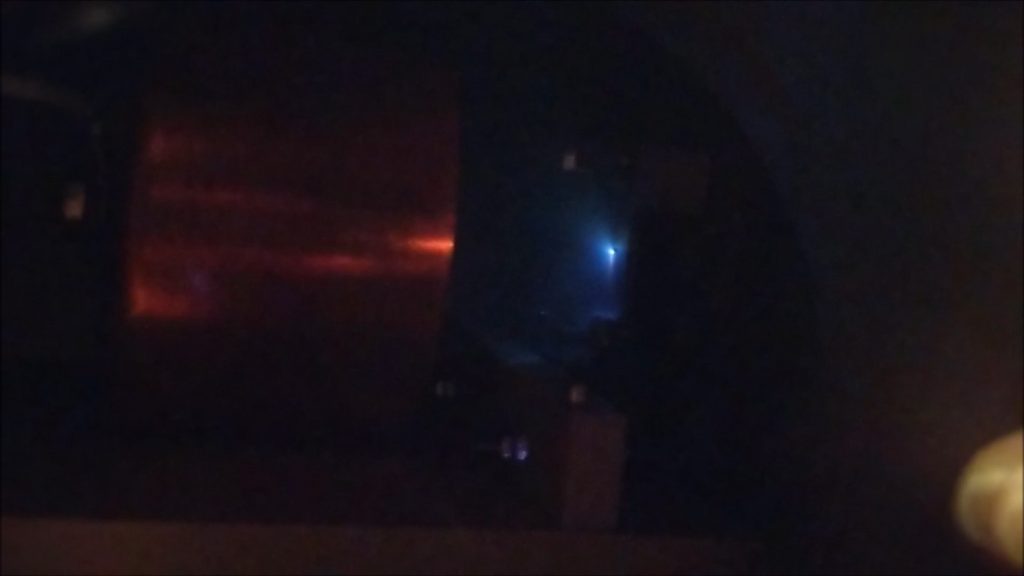
This second set of videos shows the thruster operating in peak output mode.
Assuming purely ionic emission, we can calculate some rough initial performance estimates. For thrust, let’s assume PIR with 50% monomers and 50% dimers. Averaging this for both monomer/dimer emission with EMI/BF4 beams, max theoretical thrust is around 0.24uN. Taking into consideration non-ideal real-world operational losses due to thruster inefficiencies, assuming 30% for reasonable losses, this gives an average thrust of around 0.17uN. This represents an increase in 3x the thrust at 39x beam current from the prior ignition test 4, which was estimated to have produced only 0.051uN of thrust.
For ISP, assuming the same PIR mode of operation with 50% monomers and 50% dimers, at +/-4.7kV this gives a max average theoretical ISP of ~8380s. However, in literature it has been shown that there is about a 50% discrepancy between measured ISP and theoretical max ISP, most likely due to polydispersive losses in the beam, which factored in gives a more realistic ISP of 4190s. This represents a large increase from the prior observed 3650s from ignition test 4, in which the thruster was operated at a maximum of +/-4kV.
Although these numbers are very rough estimates based on operating mode assumptions, beam current readings, and emitter operating voltages, this can give a reasonable first approximation of performance currently expected from the thruster during this test.
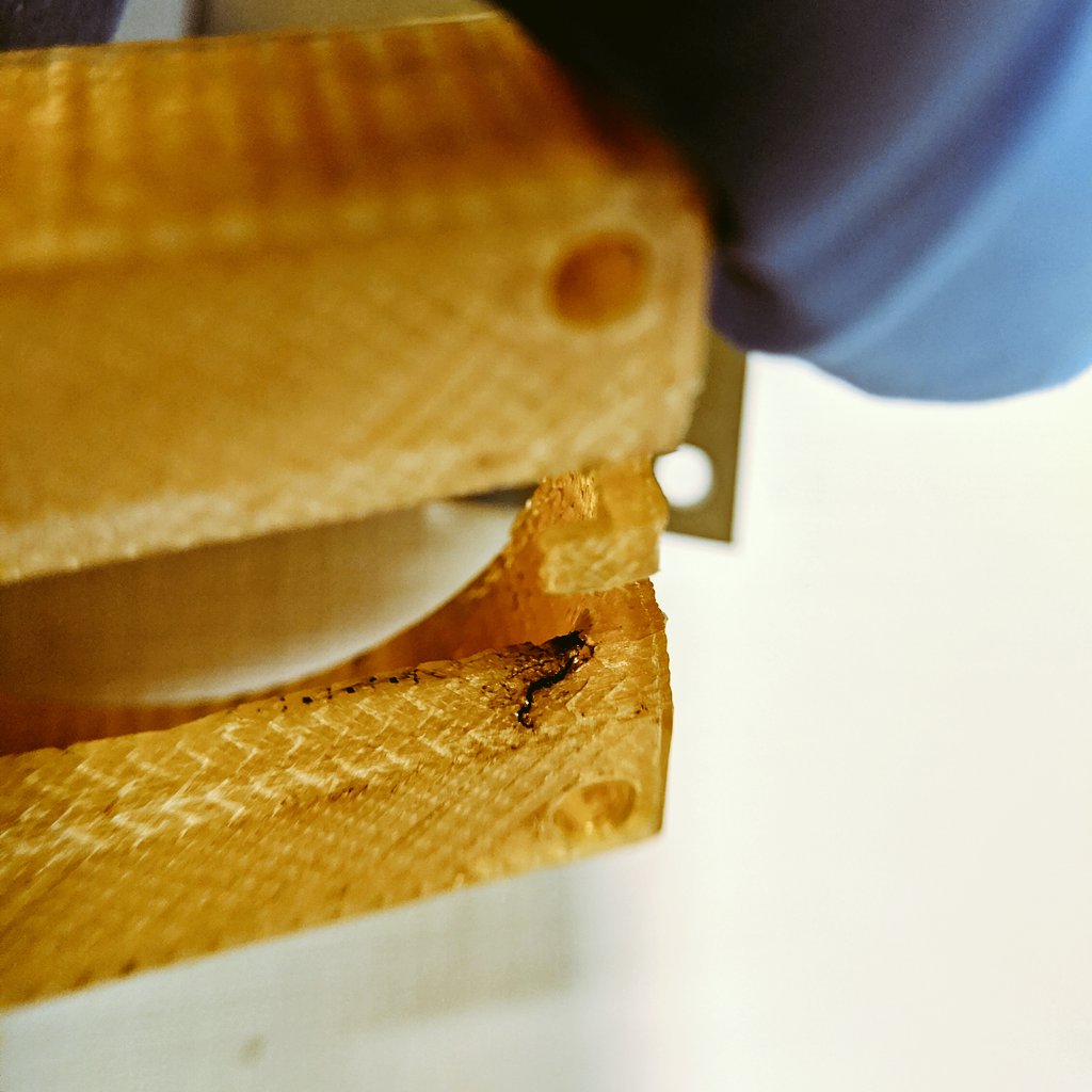
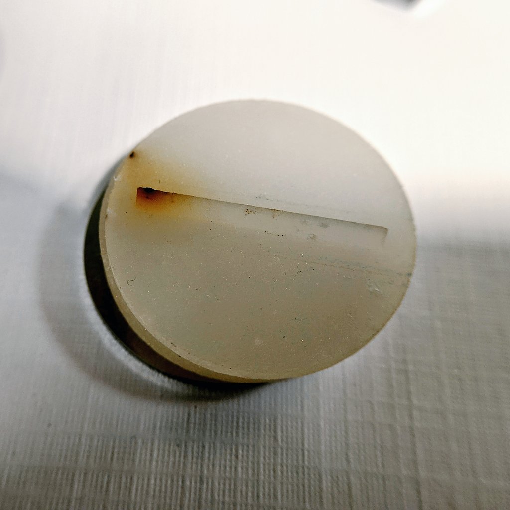
After testing, the thruster was removed in the next few days to prepare for the sixth ignition test, as well as for post test inspection. During inspection it was discovered that the cause of shorting and thruster failure was again due to liquid creep along the surface of the 3D printed Ultem 1010 housing, allowing for a conductive bridge to form between the porous glass emitter and the stainless steel extractor plate. However, surprisingly the liquid bridging and creep was found to have originated not at the emitter like in prior testing, but at the disk surface near one side of the housing, on the same side that emission was occurring!
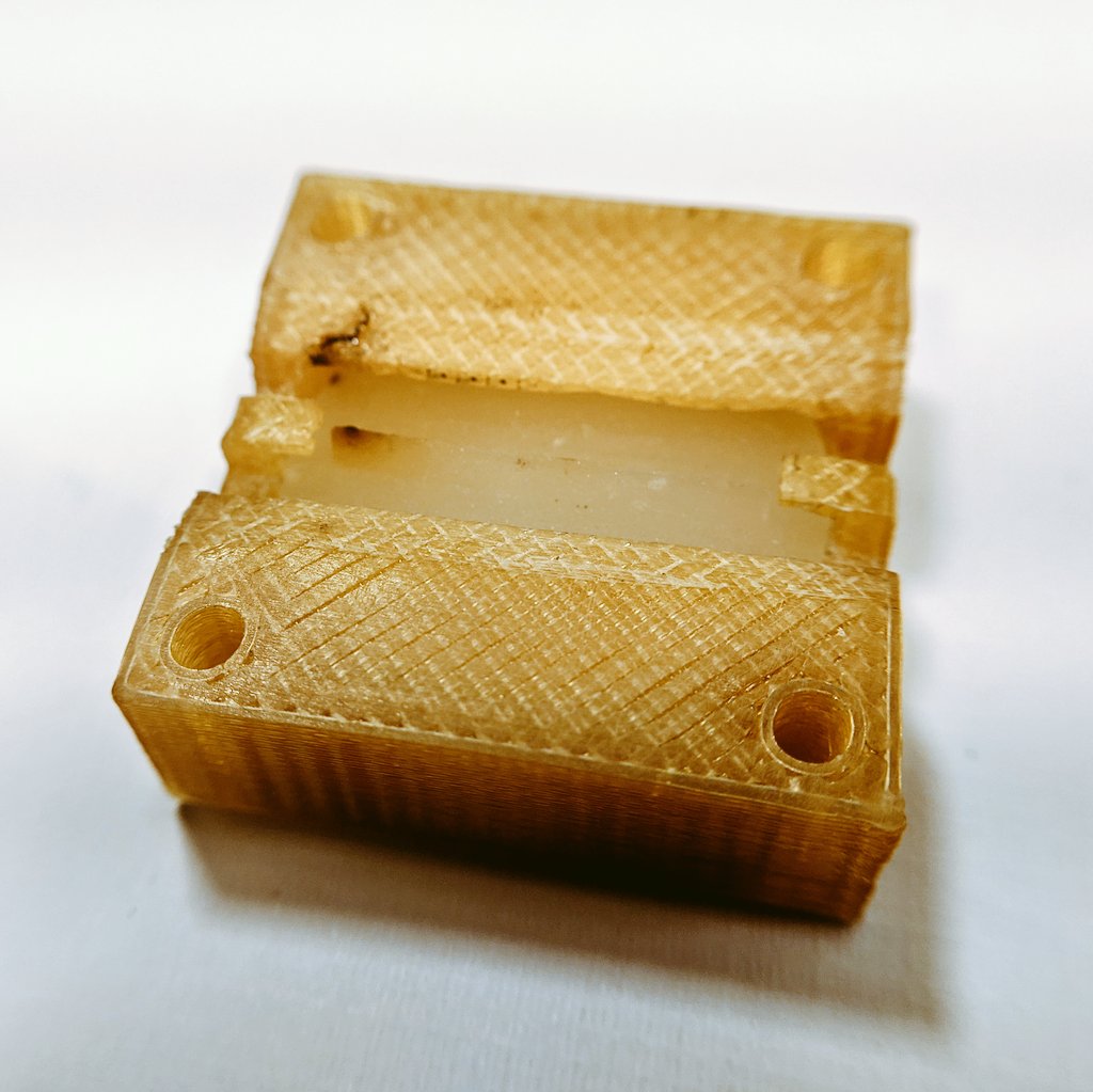
Upon closer inspection of the thruster housing, it was also found that the arcing failure occurred through the bottom of the housing which touched the emitter disc, snaking its way through the 3D printed housing.
In addition, emission was again shown to occur only at one corner of the emitter, which has proven to be a key weakness of standard linear slits as opposed to the enhanced extractor slit introduced in ignition test 3.
Although successful ignition across the ridge emitter was not achieved, this test marks a massive step forward in thruster output, operational stability, and electronics over all other prior tests with the ILIS to date. The thruster operated in its highest peak output yet, at the highest voltages stably for the longest period to date. The V6 electronics were also really put to the test, performing perfectly without any issues.
In my next post, I will review the next test of the ILIS1, where I again make another major advance in performance!
The full official test report for the fifth ignition test of the AIS-ILIS1 can be found below: