FORELINE PARAMETERS AND PUMPDOWN TIME CALCULATION FROM ATMOSPHERE TO ROUGH VACUUM
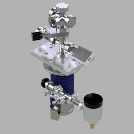
SYSTEM DESIGN V4
From the previous chapters, the major and critical vacuum parameters were explored and calculated for the V4 design. This section will cover the final main calculations for this system. This covers some of the basic foreline parameters and calculations, as well as an estimate for the pumpdown time for the system from atmosphere to rough vacuum. Below is the PDF for the various foreline parameters and figuring out the pumpdown time from atmosphere to rough vacuum:
Foreline Parameters and Roughing Pumpdown Times – Design V4
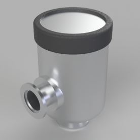
A few initial considerations should be noted for the roughing line. For the range explored, from atmosphere to about 10 microns, the load due to outgassing is negligible, and can be omitted. In addition, a well designed foreline should not have any effect on the speed of the foreline pump. Therefore, the effective speed of the system should be equal to the speed at the inlet of the pump. The foreline for this system was kept as short and minimal as possible, incorporating a necessary pressure gauge, isolation valve, and a replaceable molecular sieve foreline trap. While a foreline trap is not required, it can be greatly beneficial from keeping both the diffusion pump oil free of contamination from the roughing pump, and keep the roughing pump oil cleaner by absorbing moisture during initial pumpdown. A used trap on eBay was purchased at more than five times lower than its original cost new, and in excellent condition. Cost needed to be minimized, as well as size to make the system more compact and portable on a single mobile cart.
The first set of calculations in Section 1 of the PDF goes over finding some initial key parameters of the roughing line. First, the roughing flow regime is determined. This can fall into one of three categories: purely viscous flow, purely molecular flow, or transitional flow. This is established by the flow factor which is represented by Dp, where D is the diameter of the roughing line, and p is the mean gas pressure. Units here are cm and Torr, respectively. For this system, the diameter of the roughing line is 2.210 cm. The mean pressure is found between the starting and ending pressures – in this case, it is assumed that the starting pressure P1 is 760 Torr (atmosphere), and the ending pressure P2 in the foreline at the backing inlet of the diffusion pump is 2×10^-2 Torr, or 20 microns. Based on the boundary conditions for the Dp factor, it is verified that the roughing flow is indeed purely viscous.
Now that the flow regime is established, the equation for conductance of a pipe in viscous flow can be used to find the conductance of the roughing line. The general equation for viscous flow conductance is given in the PDF – since air at 20C is considered as the gas, this equation can be reduced to a simplified form for this gas input. The line is based off of KF25 hardware, and the diameter is assumed the same for all parts. The line is also treated as a single length line with the total length of all parts, including bends for simplicity. The conductance of the line is found to be 41,487.062 L/s. Note that this number is massively larger than other conductances previously calculated, but again, this is for an entirely different flow regime between atmosphere and very rough vacuum, where gas flow principles are much different than in molecular flows.
Once the conductance is found, then the effective speed can be calculated. First, the maximum speed of the forepump is determined. The pump speed was determined based off the minimum pumping requirements for maximum throughput of the diffusion pump from the manual. From the manual of the Edwards EO4 diffusion pump, the minimum displacement of the backing pump is 6.600 m^3/h, which converts to 3.885 CFM, or 1.834 L/s. The backing pump requirements also specify this minimum with a single stage rotary vane pump. The selected pump, a Yellow Jacket SuperEvac 93560, is a two-stage rotary vacuum pump that exceeds the backing throughput criteria. The flow rate of the pump is 6CFM, which can be calculated to 2.830 L/s. The pump selected has about 35% higher throughput than the recommended min displacement, which was also in part selected due to pump availability and cost, and should have enough overhead for the gas loads that will be seen in the system or the effects of the foreline trap (in viscous flow). Based on the equation to calculate effective speed with calculated conductance and established max speed, the effective speed was found to be almost exactly 2.830 L/s. Since the foreline conductance is so massive compared to the maximum speed of the pump, there is virtually no change in the calculated effective speed. From this, it can be shown that the conductance of the roughing pipeline in viscous flow has a negligible effect on the maximum pumping speed of the backing pump, and is indeed well planned and designed. While a more true scientific grade backing pump is usually preferable, for operating a system on a tight budget, a quality two-stage rotary vain refrigeration pump can serve as an excellent cost effective alternative, and as long as it meets the backing requirements of the main high vacuum pump, should work well in many cases.
Once the effective speed has been determined, the pumpdown time can be calculated. One of the factors required in the equation is the volume that needs to be pumped. Therefore, the total volume of the system is calculated. Because the roughing pump will pump out the entire volume of the whole system, all parts must be factored. This includes the volume of the foreline, the total internal volume of the diffusion pump, the volume of the high vacuum pipeline, and the volume of the chamber. This was determined from CAD models of the system. The total volume of all above parts was found to be about 5.464 L. Based on this volume, with a effective pump speed of 2.830 L/s, a starting pressure of 760 Torr, a final pressure of 0.020 Torr, and the ultimate pressure attainable by the forepump (from the pump datasheet) of 0.015 Torr, the total pumpdown time is found to be about 23 seconds. Based on the small size of the system, and minimized length of the foreline and high vacuum pipeline, as well as the speed of the pump, this would seem like a very reasonable number to expect.
This chapter effectively concludes the major engineering design calculations for this system, as well as this walkthrough guide on the full initial high vacuum design of the V4 System. Hopefully this short engineering design series will help in aiding the design process of high vacuum systems, especially for those operating on tight and limited budgets. Knowing the critical factors of a system such as ultimate pressure, maximum gas loads, effective speeds, and system conductances gives valuable insight to the system operation, as well as establishes the anticipated operating parameters, which ultimately helps to better design a more effective system.