CALCULATIONS FOR CONDUCTANCES AND EFFECTIVE SPEEDS IN MOLECULAR FLOW FOR VARIOUS PROCESS GASES
SYSTEM DESIGN V4
SECTION 1 – Design Overview
As of the present time, design V4 is the current design of the Small Scale Multipurpose High Vacuum System that will be implemented. All calculations going forward after this section will refer to the numbers for this design.
As mentioned in the previous Chapter 03.4, a baffle and additional adapter plate was needed to reduce or eliminate backstreaming from the diffusion pump due to the operating pressure of the backing line and pump. These additions constitute the design change from design V3 to design V4. As also mentioned prior, the high vacuum pipeline has been reduced to the shortest possible path, and as a result, the speeds and conductances found for V3 are the highest practical values attained. Since V4 will be adding the baffle and the adapter plate, these numbers will be reduced – however, you will see that the change is incredibly small, resulting in nearly the same conductance and speed, despite extra components and length being added to the pipeline.
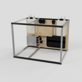
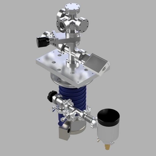
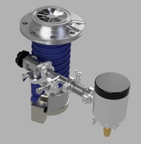
Below is a CAD render of the current V4 design. Due to the top adapter and mounting plate, it is not really possible to see the adapter and baffle very well, so two views were included – one of the complete system, and one of the upper portion removed, exposing the diff pump, baffle, and adapter plate.
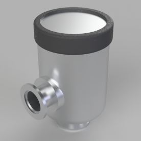
The baffle and the adapter plate are designed to be clamped between the diffusion pump flange and the top aluminum mounting and adapter plate. The aluminum selected for the adapter plates is ATP-5 tooling and jig plate. The aluminum is machined to an absolute maximum surface roughness of 25 micro-inch. In a paper detailing the general design overview of high vacuum chambers for NASA for testing, the maximum recommended surface finish of a flat plate and mating glands for o-rings should be better than 32 micro-inch, whereas rotating feedthrough shafts on o-rings should meet or exceed a surface roughness of 16 micro-inch. ATP-5 exceeds this design criteria for flat mating surfaces, and makes the process much easier since surface preparation and machining would not be required, as opposed to buying standard aluminum plate stock. ATP-5 is also reasonably cost efficient, and the design of the plates makes it simple to fabricate. An excellent and very low cost supplier for this plate can be found here, which was the supplier used to purchase the plate stock for this system (US based company):
SECTION 2 – Calculations for Determining Conductance and Effective Speed in Molecular Flow
The calculations for V4 were applied in the same exact manner as for V3 and V2, the only major difference was calculating the conductance for the new baffle and adapter plate added to the V3 calculations. Below are the PDFs for reference for design V4 calculations for molecular flow:
2.75″ Conflat High Vacuum System – Design Iteration 4 – Molecular Flow – AIR
2.75″ Conflat High Vacuum System – Design Iteration 4 – Molecular Flow – ARGON
2.75″ Conflat High Vacuum System – Design Iteration 4 – Molecular Flow – DEUTERIUM
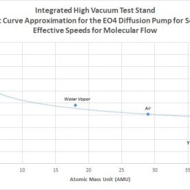
2.75″ Conflat High Vacuum System – Design Iteration 4 – Molecular Flow – WATER VAPOR
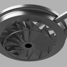
For the water cooled baffle, the conductance can be approximated by calculating the conductance of the baffle as if it were first just an equivalent diameter short section of an open pipe section. The regular correction factors are then applied. However, for a well-designed optically opaque baffle, the conductance should be reduced to a value of about 50-60% of the speed for use with an appropriately matched pump. Therefore, the number calculated for the equivalent open short section, with correction factors, was further corrected to a value of about 50% of this value.
Based on the calculations, the following conductances and speeds for the new design for air, argon, deuterium, and water vapor were obtained:
AIR:
- Conductance – 13.834 L/s
- Effective Speed – 13.522 L/s
ARGON:
- Conductance – 11.741 L/s
- Effective Speed – 11.516 L/s
DEUTERIUM:
- Conductance – 52.471 L/s
- Effective Speed – 49.241 L/s
WATER VAPOR:
- Conductance – 17.541 L/s
- Effective Speed – 17.043 L/s
As can be seen from the prior system V3 numbers, the conductances an effective speeds are only slightly less – about 1 L/s for air, argon, and water vapor, and about 3-4 L/s for deuterium. The conductances of the baffle and the adapter plate are still so large compared to the choke point conductance of the system, which adding these components results in only a small change. Therefore, even though slightly more cost and complexity was introduced into the system, the speeds and conductances were successfully kept to almost the same as the practical maximum value. Therefore, the system is much better protected from backstreaming, although the cost will be in high outgassing loads due to the extra o-rings, which will be covered in the following sections.
This concludes Chapter 3 of this blog walkthrough, covering the design iterations from V2 to V4, and illustrating the differences in calculated conductances and speeds for the molecular flow regime for various process gases, as well as engineering design trade-offs, benefits, and costs between each system, based on the initial criteria and parameters. Going forward from here for the remaining chapters, numbers will be calculated only for the V4 design. The next section to be covered will go into transitional flow calculations. From transitional flow calculations, which are initially derived from molecular flow, the numbers for ultimate vacuum, outgassing rates, and operating gas flows can be calculated..