In my previous post, I reviewed the fifth ignition test of the AIS-ILIS1 ionic liquid electrospray thruster, which ended up being my biggest leap forward yet. In this post, I review the details of the next test for the thruster, occurring on 08/21/2020. This test marked yet another major leap in development, outperforming all other tests prior!
During the prior ignition test 5, the ILIS1 was run with the standard 0.75mm wide linear slit extractor, achieving average beam current of 0.5uA with a peak output of 2uA. However, emission was concentrated at one corner of the porous glass ridge emitter. In order to increase field enhancement and more uniform field distribution across the length of the porous glass ridge emitter, eliminate emission at the corners, and increase overall thruster output, the new enhanced extractor design was used, which incorporates flared aperture ends at the corners, and a narrower central slit region at 0.5mm wide. The original extractor plate was 0.1mm thick, where the new plate was increased to 0.25mm thick.
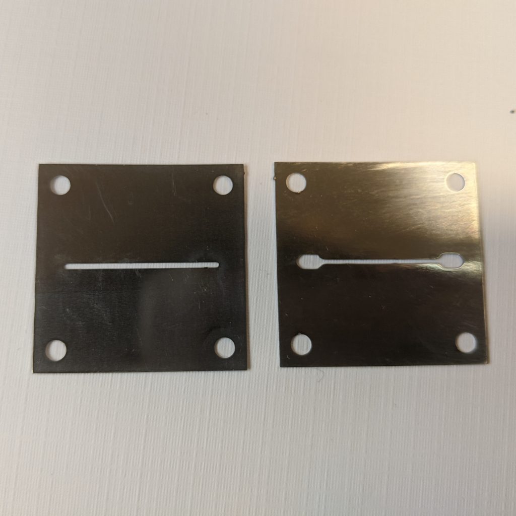
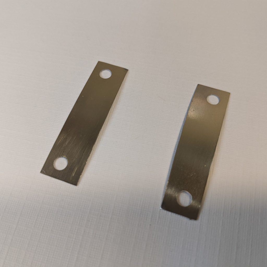
During the third ignition test, this same extractor was used, however it was found that spacing was too tight with 0mm vertical clearance between the top of the emitter and the bottom of the extractor plate aperture, causing immediate shorting and failure of the thruster. To compensate, 0.1mm shims were used, cut from a spare extractor plate, to increase the vertical spacing between the emitter and extractor to 0.1mm.
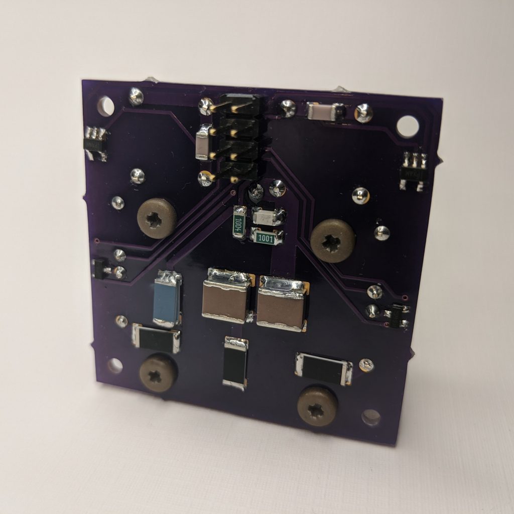
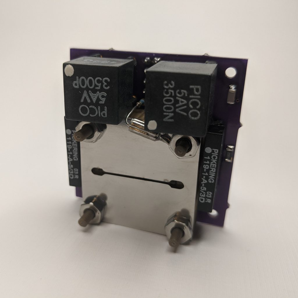
During the prior test, the new V6 board was also qualified for the first time at extended operation at high voltages of up to 4.8kV without any issues during testing. This far exceeds the original design specifications of 3.5kV, and is attributed to the addition of new 100k surge protection resistors placed between the outputs of the HV relays and the HV emitter contact pad, the HV filter capacitor and HV emitter contact pad, and the extractor and ground.
After the new extractor plate was polished and cleaned, the ILIS1 was taken out of the vacuum chamber, which was still held to roughing levels from the prior test earlier that day. Due to operation of the thruster during the prior test, fuel charring was present on the edge where emission occurred, as well as on the housing where liquid creep and eventual arcing occurred. Both of these areas were carefully cleaned to remove all traces of burnt fuel.
The thruster was re-assembled, with the emitter and extractor centered and aligned by sight, with the addition of the two 0.1mm vertical shims, running parallel with the ridge across the two top mounting holes and two bottom mounting holes. While prior attempts to align the 0.5mm slit by eye proved to be a significant challenge, the addition of the 0.1mm shims, as well as practice over several tests, made alignment significantly easier and more reliable.
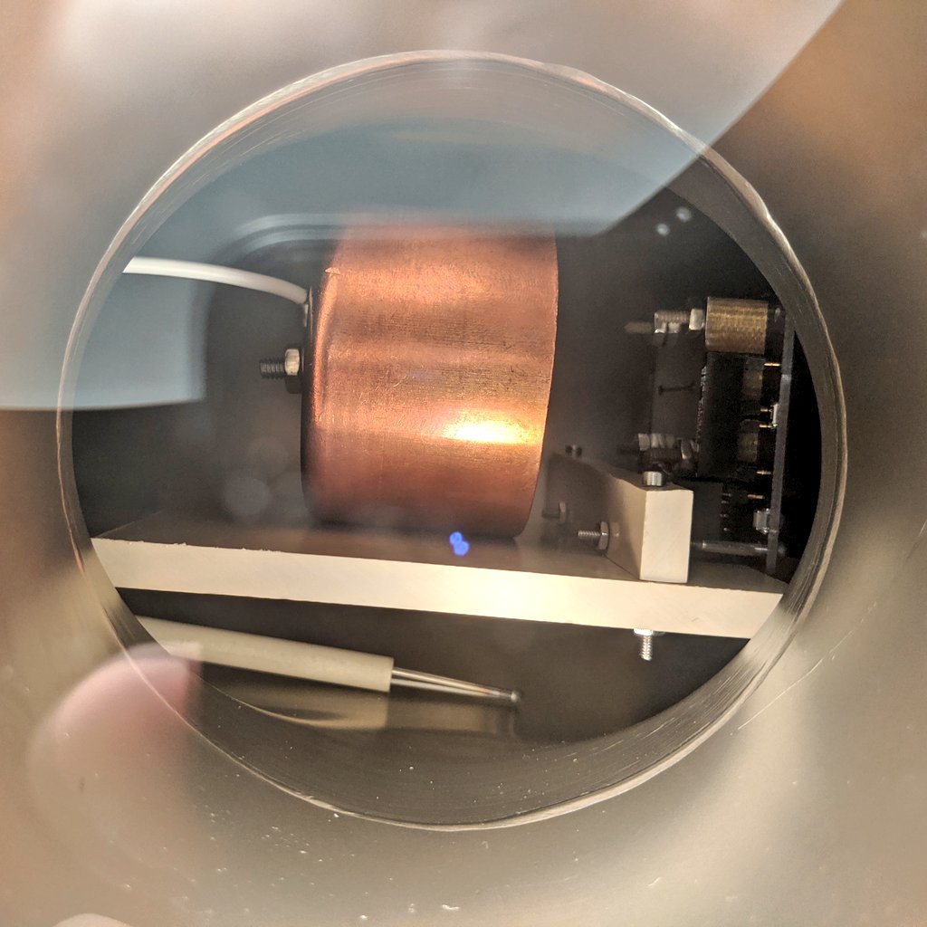
The thruster was then mounted to the Faraday cup test stand, and the assembly was mounted into the micro propulsion testing chamber, centered in full view in the 6” conflat viewport, and wired up for thruster power and control.
Since only the extractor was changed between the prior test and this test, and the thruster was held in vacuum until the extractor swap, fueling and bakeout was not necessary to prepare for this test. The chamber was evacuated to a pressure of 1.9×10^-5 Torr before starting up the thruster. The thruster was first started with an initial warm up phase for a period of 10 at minimum power in manual monopolar mode, first with +HV for several minutes, then switching to –HV to make sure the circuit was operational as expected and to establish minimum output.
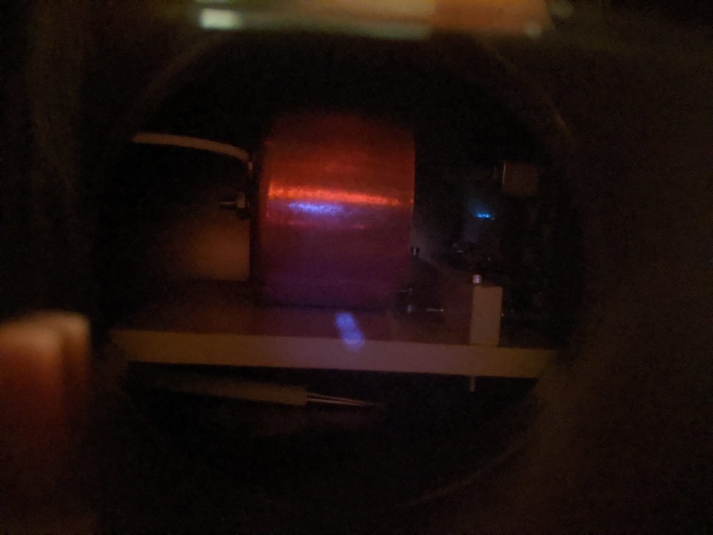
Power was slowly increased until an incredible observation was made: visible glow across the central region of the emitter, confirming not only success of the new enhanced extractor design, but that stable multi-mode emission was being achieved across the central region of the emitter for the first time!
After the initial warm up phase, the thruster power was further increased for another 5 minutes prior to switching to bipolar operation. Once stable emission was confirmed, thruster control was set to automatic bipolar mode at 30 seconds per polarity, with a 2 second interval between polarity transitions. Input voltage to the thruster was slowly increased until the output readout indicated the thruster was operating at +/-3.7kV. Readout from the oscilloscope looking at the Faraday cup with 100k shunt resistance was at +/-50mV, indicating +/-500nA of beam current. This was consistent with the prior test nominal emission levels, except this time emission was along several regions across the central portion of the slit, instead of one corner.
During the course of the first 40 minutes of operation, thruster output fluctuated, rising and lowering until stabilizing out at +/-500nA at an increased voltage of +/-4.6kV. The thruster plume glow had reduced in intensity by this point, however emission remained at stable levels.
After 1 hour of operation in this mode, thruster cycling times were decreased to 10 seconds per polarity with a 1 second transition between polarity reversals. After a few minutes, the cycling time was further reduced to 5 seconds per polarity with a 0.5 second transition. After another 10 minutes, the thruster cycling time was further reduced to 3 seconds per polarity with a 0.5 second transition time. At this cycling frequency, some instabilities were seen in both beam as well as occasional glitching of the controlling, requiring several reboots due to the Arduino crashing. Some arcing was observed inside the 3D printed housing, however emission continued.
After another 5 minutes of operation, emitter current significantly increased to almost 5uA of beam current on the positive cycle, although the negative cycle seemed to be lagging by less than half that value. At this point the voltage had increased to +/-5kV, the highest values run yet with the ILIS1 board. Finally, after 5 minutes of operation in this higher mode of emission, emission ceased with evidence of arcing between the emitter and extractor, confirmed visually and with thruster readouts. Thruster power was shut down, and the test was ended. One wild ride to the most successful test yet of the ILIS1!
During the test, video was captured of thruster operation, showing clear multi-site emission across the central region of the slit. In this first video, we see part of the conditioning phase, where only single site emission occurs before the thruster turns on more completely.
In this second video, the thruster is seen running in a higher mode of emission in bipolar operation. Interestingly during this test phase, there was unequal emission intensity between the positive and negative voltage cycles. Throughout the video, numerous polarity transitions can be seen, where the thruster switches from positive to negative, therefore changing from a +EMI ion beam to a -BF4 ion beam, extracted from the EMI-BF4 ionic liquid fuel inside the porous glass emitter. During one polarity, emission is significantly higher than the other, accompanied with an additional glow from the 3D printed Ultem 1010 housing. Both single site and more uniform multi-site emission can be observed during this video.
In this third video, the thruster is seen running in a higher mode of emission in bipolar operation. After conditioning from the first two prior videos, the thruster is now seen operating in a more stable multi-site emission mode, with even emission between positive and negative polarity beams. During the video, a polarity transition can be seen, where the thruster switches from positive to negative, therefore changing from a +EMI ion beam to a -BF4 ion beam, extracted from the EMI-BF4 ionic liquid fuel inside the porous glass emitter. Multi-site emission is clearly demonstrated, where turn-on of the porous glass ion emitter is more complete, and operating stably in bipolar mode.
Finally in this last video, the thruster is seen running in a higher mode of emission. Multi-site emission is clearly demonstrated, where turn-on of the porous glass ion emitter is more complete, and operating stably in bipolar mode.
Assuming purely ionic emission, we can calculate some rough initial performance estimates. For initial thrust estimates, let’s assume PIR with 50% monomers and 50% dimers. Let us first examine stable operation at 500nA of beam current. Averaging this for both monomer and dimer emission with EMI/BF4 beams, max theoretical thrust is around 0.06uN. Taking into consideration non-ideal real-world operational losses due to thruster inefficiencies, assuming 30% for reasonable losses, this gives an average thrust of around 0.04uN. Now looking at the peak beam current of 5uA, with the similar assumptions stated above, this gives us a rough corrected peak thrust estimate of around 0.4uN, the highest thrust recorded yet for the ILIS1.
For ISP, assuming the same PIR mode of operation with 50% monomers and 50% dimers, at +/-4.6kV during stable emission at 500nA of beam, this gives a max average theoretical ISP of around 8288s. However, in literature it has been shown that there is about a 50% discrepancy between measured ISP and theoretical max ISP, most likely due to polydispersive losses in the beam, which factored in gives a more realistic ISP of 4144s. Now looking at the peak emitter potential of 5kV, factoring in the same assumptions stated above, this brings the rough corrected peak ISP estimate to 4320s, which is the highest estimated ISP to date for the ILIS1.
Although these numbers are very rough estimates based on operating mode assumptions, beam current readings, and emitter operating voltages, this can give a reasonable first approximation of performance currently expected from the thruster during this test.
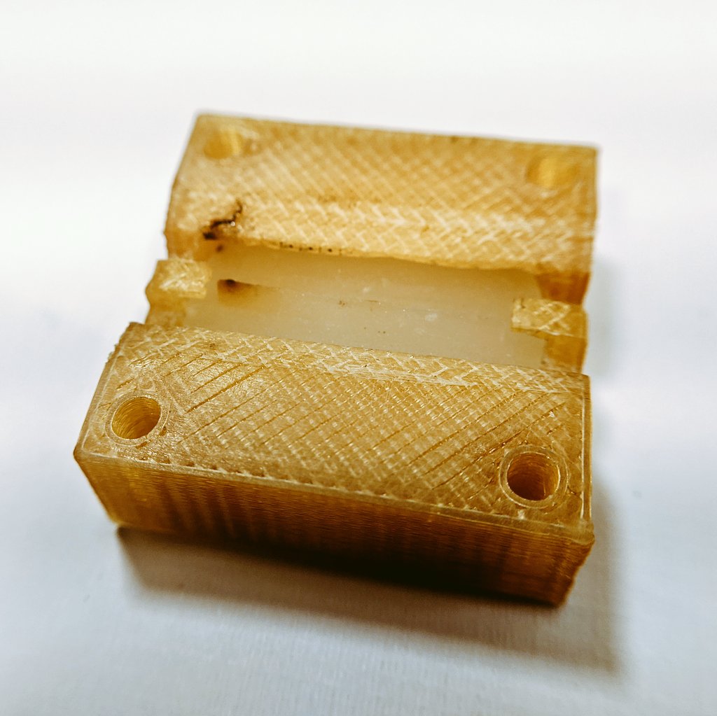
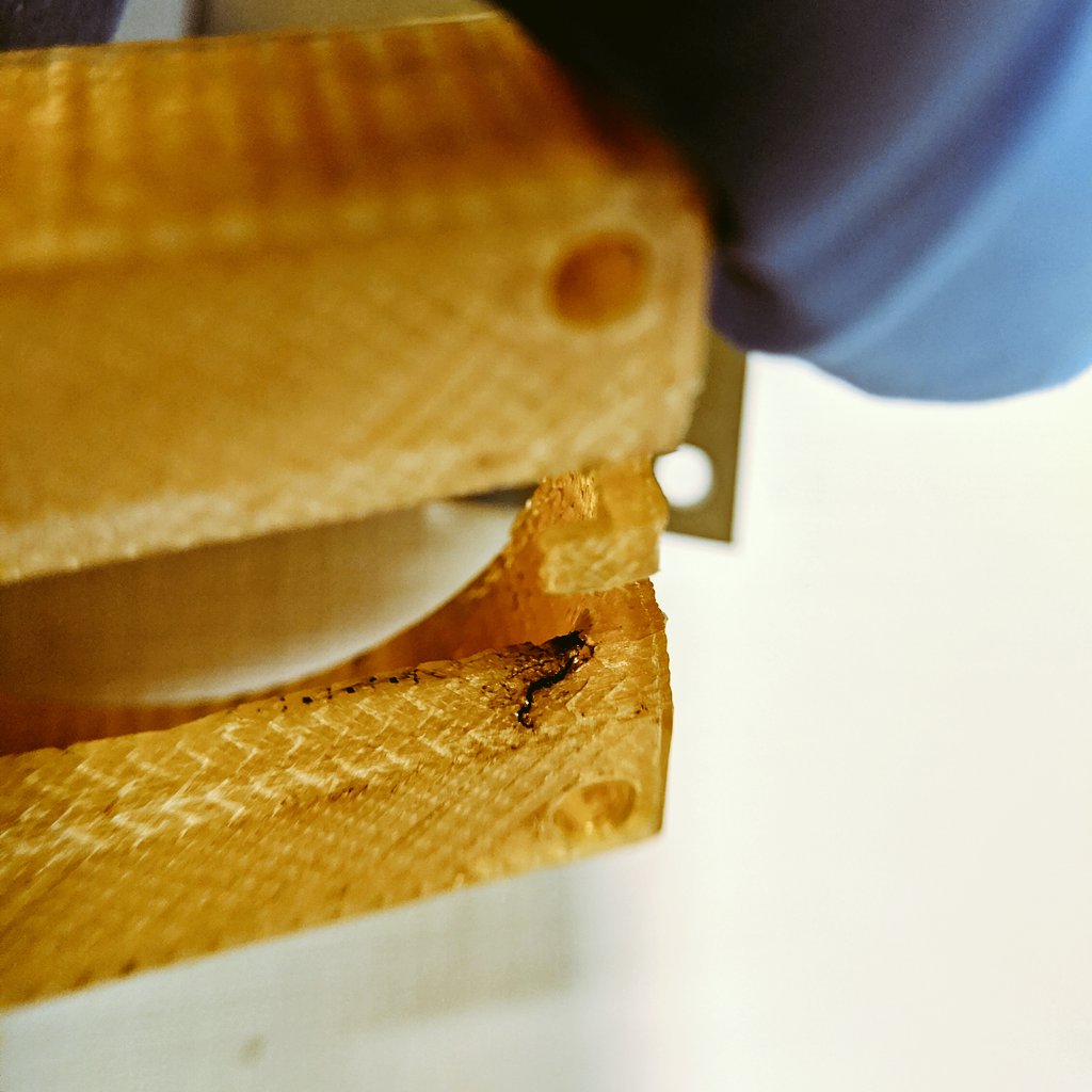
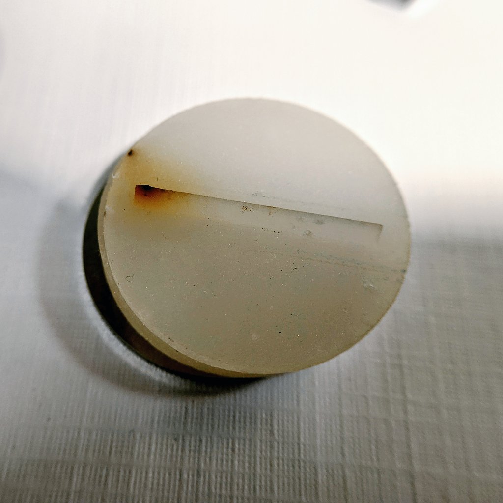
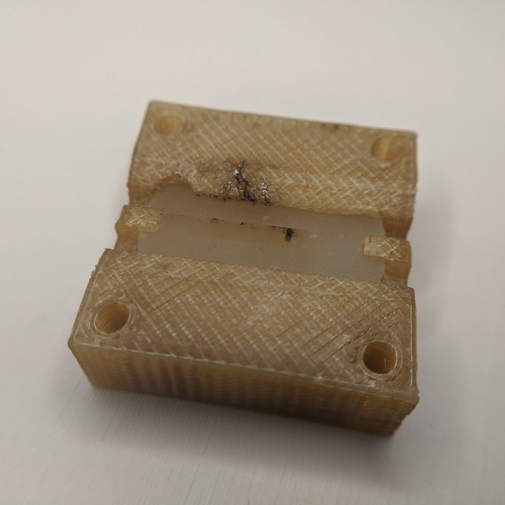
After a couple of weeks at low vacuum levels after testing, the thruster was removed for post-test inspection. During inspection it was discovered that the cause of shorting and thruster failure was again due to liquid creep along the surface of the 3D printed Ultem 1010 housing, allowing for a conductive bridge to form between the porous glass emitter and the stainless steel extractor plate. This liquid bridging and creep was found to have originated at the disk surface near one side of the housing. This failure is consistent with the prior test during peak thruster operation. This calls for further optimization and careful redesign considerations for the thruster housing going forward, as this is the biggest lifetime limit for the ILIS1 to date.
In addition, minor charring was observed along the ridge of the thruster. Fuel darkening was seen along the central region of the emitter, with no charring or evidence of emission at the corners, again confirming the successful operation of the new enhanced extractor geometry.
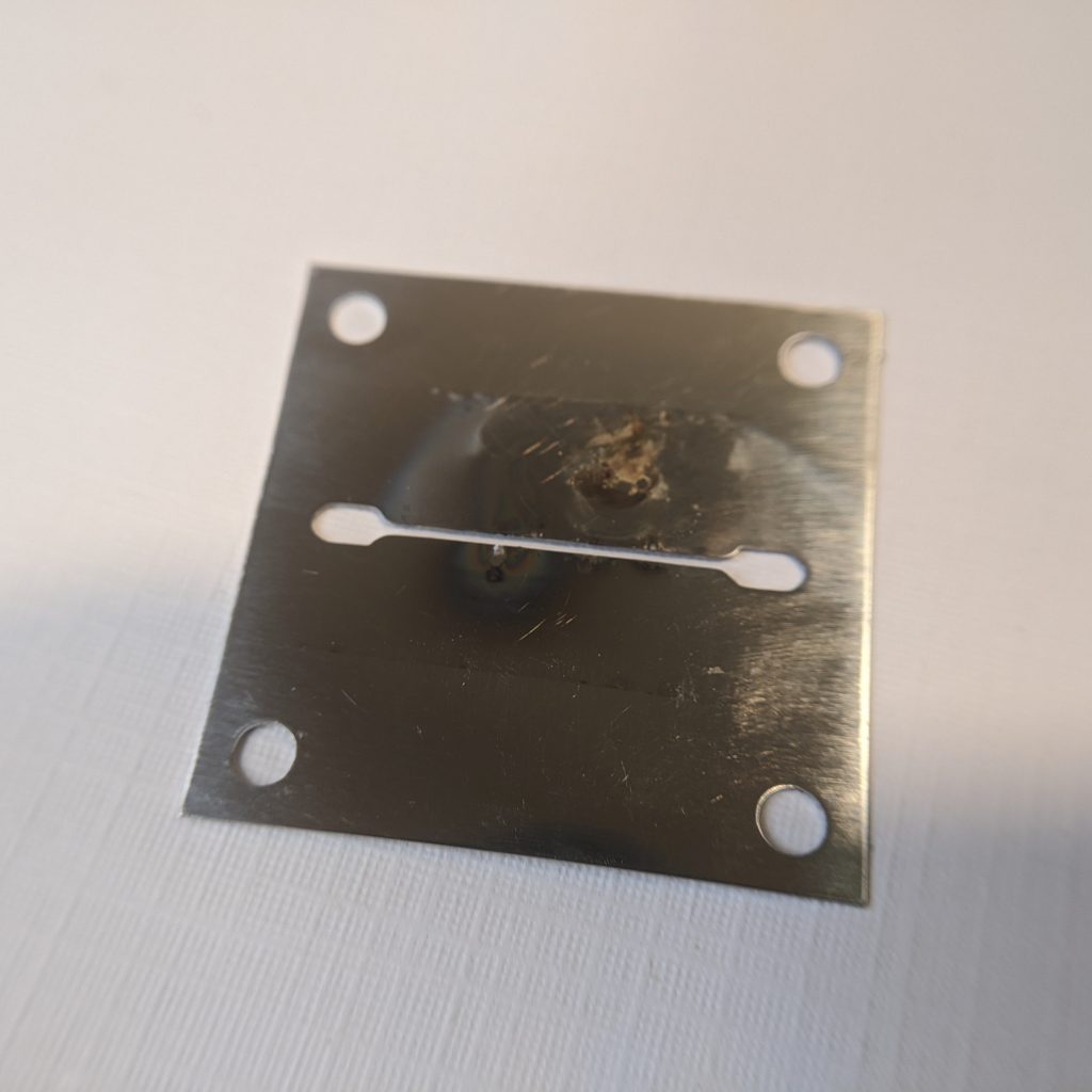
Inspecting the extractor electrode, corresponding areas of bombardment due to beam intercept, as well as fuel charring can be see, both long the emitter as well as where liquid creep occurred from the disc and along the surface of the thruster housing to the extractor.
The official test report for ignition test 6 of the AIS-ILIS1 ionic liquid electrospray thruster can be found below:
With this test, I have pretty much maxed out what I can do with this emitter design. I really need sharper edges and higher field enhancement to bring emission up much more at lower voltages. This thruster put on a hell of a show, and was my first steps into ILIS electrospray. The high voltage and control electronics have also been really put to the test, passing with flying colors. I drove them far beyond their rated specs, and it just bulldozed it’s way through these past 4 tests like it was nothing. I think a big key was the new surge limiting resistors as well as better control and conditioning sequences.
I will be officially ending development on the ILIS1, and shifting focus on the new ILIS2 design which is already underway, the next generation of the AIS-ILIS1 series thruster development. This will include a brand new emitter geometry hopefully aimed at max emission of hundreds of uA. The new design for the ILIS2 is already underway, and I will be reaching out to various sources for quotes and lead times for this new porous glass emitter array. Unfortunately it will most likely take a few months, but I’m looking to break new ground with this next iteration.
It’s been quite a ride. Brute forcing this tiny thruster to work, one test at a time, each time bringing me closer to realizing this system. From small steps to bounds, I went from barely working electronics to my first steps of stable operation. This has been a massive learning experience, not only in the tech itself but hands on assembly, testing, troubleshooting, and sitting right in the pilot’s seat and operating the thruster, successfully firing as far as I am aware the first PQ ion thruster ever built, right at home! This new phase with the ILIS2 will hopefully be the beginning of the first truly deployable PQ compatible ILIS thruster, with full thrust, ISP, and lifetime. AIS is now in the race, the biggest underdog, for ILIS with all the big shots. The ILIS2 is coming with a vengeance.