CALCULATIONS FOR CONDUCTANCES AND EFFECTIVE SPEEDS IN MOLECULAR FLOW FOR VARIOUS PROCESS GASES
SYSTEM DESIGN V3
SECTION 1 – Design Overview
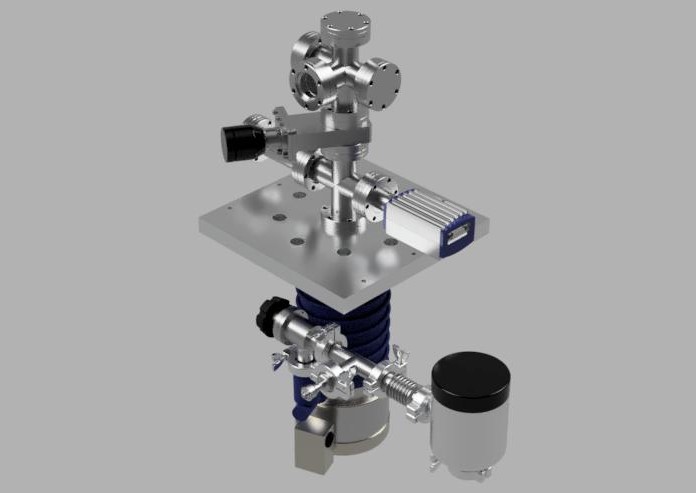
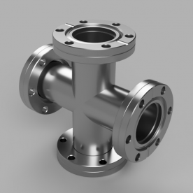
As mentioned in Chapter 03.1, the conductances found for system V2, while appearing adequate for deuterium, were too low for heavier gases. In order to increase the effective speed, the total conductance of the system needed to be increased. As can be seen from prior posted models, the pipeline is already incredibly short – a couple of small valves and a four way cross. Reducing the length at this point will not practically help the speeds. Instead, efforts needed to be focused on the choke-point of the system. In design V2, this was the inline valve. The best way to effectively combat this is to utilize a valve with the highest possible conductance, which allows for sealing at high vacuum levels. This turns out to be a gate valve. Unfortunately, gate valves, even for 2.75” CF hardware, are usually either quite expensive, or can be difficult to locate on eBay. Fortunately, by a stroke of luck, a free one was obtained from an old vacuum system that was being scrapped at a research facility. On top of this, the gate valve was manual, allowing to eliminate the butterfly valve and have full conductance control using the gate valve instead. From design V2 to design V3, this was the major change – two valves from the prior design were replaced with a single valve for the new design, which not only greatly increased conductance, but allowed for conductance control, isolation, and without increasing the expenses for this system. Below is a CAD rendering of the new V3 design:
An additional change to note is the change of placement of the valve. Instead of having the valve located at the base near the adapter plate, it was decided to move this directly under the chamber. This is due to the fact that from the adapter plate to the 2.75” CF hardware, a Viton gasket is needed. Due to the way the bolt holes are set in the gate valve, it would be impossible for to tighten it to the baseplate, which also utilizes blind tapped holes. Moving it between the 5 way cross chamber and the 4 way cross pipeline was the best compromise for the system layout. It also serves an additional purpose for pumping at higher vacuums. For long conditioning runs, ideally an ion pump would be switched over after high vacuum was reached from the main diffusion pump, so the chamber can be continuously pumped, conditioned, and bake out while drawing next to no power and requiring little maintenance or worry, where it would be problematic to run a diffusion and roughing pump for weeks continuously. The valve would effectively isolate the main chamber from the pipeline to allow for this pumping, in addition to allowing the pipeline to be re-evacuated with the diffusion pump. Also, ion pumps can be used simultaneously as ion gauges, which allows the upper portion to be monitored. The pipeline will be monitored by other instrumentation on the cross.
Another major change to the design was the decision to remove all KF hardware on the high vacuum side. While KF hardware can still achieve high vacuum levels, it was decided to reduce as many sources of outgassing and permeation as possible near the chamber. The pipeline currently will support two high vacuum gauges mounted to 2.75″ conflat flanges.
Finally, design choices and components were selected for the roughing side as well, and modeled as shown above. Since the roughing pump was already selected, a way of connecting it to the roughing inlet of the diff pump was needed. A simple manual 90 degree KF25 isolation valve is connected to the diff pump roughing inlet, followed by a three-way tee that splits to the line and to a thermocouple gauge mounted to a KF25 adapter, which would allow for measuring the pressure as close as possible to the diff pump inlet. A very short bellows section of about 3-4″ was selected to allow for a very short connection line, and give some placement flexibility for mounting the two pumps. One concern using oil-sealed roughing pumps, such as refrigeration pumps, can be the backstreaming from the roughing pump to the diff pump, which can contaminate the diff pump oil. In order to mitigate this, a molecular sieve filled replaceable foreline trap was selected. The molecular sieve not only helps prevent oil contamination, but has the added benefit of absorbing water vapor pumped from the diffusion pump which could in turn contaminate the roughing pump oil. In essence, both paths to and from either pump is reasonably well protected. With a bit of patience and searching on eBay, these traps can be bought for very cheap. The particular one found for this system was obtained for $80.00, where an equivalent new one would cost around $500.00 from major vacuum suppliers. The trap obtained arrived used, but in quite excellent condition. Molecular sieve refill, usually of zeolite, alumina, or other adsorbents, can also be purchased relatively cheap – a pound of it was purchased for about $24.00 from LDS Vacuum.
SECTION 2 – Calculations for Determining Conductance and Effective Speed in Molecular Flow
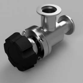
The calculations for V3 were applied in the same exact manner as for V2, the only major difference was calculating the conductance for the single gate valve as opposed to the inline valve-butterfly valve combo. Below are the PDFs for reference for design V3 calculations:
2.75″ Conflat High Vacuum System – Design Iteration 3 – Molecular Flow – AIR
2.75″ Conflat High Vacuum System – Design Iteration 3 – Molecular Flow – ARGON
2.75″ Conflat High Vacuum System – Design Iteration 3 – Molecular Flow – DEUTERIUM
2.75″ Conflat High Vacuum System – Design Iteration 3 – Molecular Flow – WATER VAPOR
The resulting conductance of the new gate valve has higher conductance than the butterfly valve fully open, more than double the conductance of the inline valve, and more than double the combined conductance of both the inline and butterfly valve. Because of this, the new choke-point of the system shifted to the 2.75” CF cross. Since the 2.75” cross is about the shortest the pipeline can practically be made with instrumentation, this represents the limiting conductance for the high vacuum pumping system. All effective speeds are then restricted to lower than this value.
Based on the calculations, the following conductances and speeds for the new design for air, argon, deuterium, and water vapor are as follows:
AIR:
- Conductance – 14.851 L/s
- Effective Speed – 14.492 L/s
ARGON:
- Conductance – 12.647 L/s
- Effective Speed – 12.386 L/s
DEUTERIUM:
- Conductance – 56.327 L/s
- Effective Speed – 52.622 L/s
WATER VAPOR:
- Conductance – 18.831 L/s
- Effective Speed – 18.258 L/s
Notice how the difference of a single valve has now almost doubled the total conductance and effective speed of the system. Deuterium rates in particularly are now noticeably higher. However, at this point, for pumpdown, the single most important gas to be concerned with is water vapor (at least until about 10^-8 Torr, which then transitions to hydrogen for the dominant outgassing load), and it is the values for water vapor that will be used to further derive the ultimate vacuum of the system. The other gases will factor in after to establish max gas loads for varying vacuum levels, in addition to the load due to water vapor. Because the vacuum line can really not get practically shorter, these are the practical maximum speeds and conductances for this system.
As mentioned in prior posts however, a potentially large gas load will need to be accounted for since a diffusion pump pump will be used, which is the gas load due to backstreaming. If the backing pressure of the diffusion pump is held to a level of around 10^-4 Torr, backstreaming becomes negligible on its own. However, the 2-stage refrigeration pump used for backing will only be able to practically achieve a vacuum at the backing inlet of around 0.015-0.020 Torr, which is not low enough to be below the critical pressure to eliminate backstreaming. Since the pipeline is also as short as possible and direct to the chamber, it could be easier for backstreaming to contaminate the surface, as opposed to having multiple bends or a very long bellows line. As a result, a water cooled baffle is required. Fortunately, one for this system was obtained for only $20.00 through networking on fusor.net.
At this point, design tradeoffs need to be considered. With the baffle, backstreaming at the roughing pressures can be eliminated, keeping the system cleaner and allowing a higher ultimate vacuum to be achieved. The cost however is additional money, an additional adapter plate, and two additional large diameter viton o-rings. The baffle and adapter plate will lower the conductance and speed of the system a bit. Adding these viton o-rings could present a problem as they greatly increase both the gas load due to outgassing, as well as set a practical limit on ultimate vacuum due to permeation. This can however be mitigated or eliminated with concentrically placed o-rings with a gap pumped between the main sealing ring and the secondary o-ring to at least 10 Torr, or by cooling the entire o-ring between the flanges to below 6C. However, since the o-rings are located right near the throat of the diffusion pump at areas with large conductances, they will effectively see much higher pumping speeds than if there were viton o-rings placed at the top around the main chamber, like in prior designs. This will help in dealing with the extra gas load, however the total gas load due to these o-rings will still need to be calculated to determine the ultimate vacuum. Despite the costs, the benefits seem well worth it based on the initial design criteria and goals.
The next chapter will outline the new and final design for this chamber, version V4, with the new baffle and adapter plate modeled and calculated.

