I. INTRODUCTION
Physics and experimental science equipment are exceptionally complex, and often require a diverse range of engineering disciplines. Whether it is semiconductor fabrication, sputtering, fusion research, ion beam systems, space propulsion, or some other complex process, the system will necessitate a strong multidisciplinary approach as well as system integration. This can be particularly daunting for the individual engineer or hobbyist experimenter, especially as the system grows more complex and requires increasing specialization and more in depth knowledge. For the average person, there is only so much time one can realistically devote to learning, and it is not possible to become an expert at all fields. Doing as thorough and intensive research and design prior to a project is crucial for its success, but it is always possible to miss a key aspect that could range from slightly less than desired performance to a catastrophic oversight causing major redesign. Fortunately, even these large mistakes provide very valuable learning opportunities and a chance to gain new engineering knowledge, albeit at a price (time, money, and frustration.) We will look at an example of major system oversight, leading to a complete system redesign, and how this initial mistake ended up making an opportunity to significantly improve the original system.
The system that we will be examining is the closed loop diffusion pump cooling system currently under development at Applied Ion Systems. This cooling system is one of many subsystems that make up the complete high vacuum test station for charged particle beam and electric space propulsion research. The entire system itself can be broken up into the following key subsystems:
- Low Vacuum Roughing System
- High Vacuum Pumping System
- High Vacuum Chamber
- Cooling System
- Low Voltage Power
- Control System Hardware
- Control, Instrumentation, and User Interface Software
- Test Stand
- Pulsed Power/High Voltage Power
- Charged Particle Beam/Plasma Device
As can be seen, the entire system requires a wide range of system integration, along with a highly technical and specialized knowledge-base in several key areas. For myself personally, I have a great deal of experience with high vacuum system design, and my specialization mainly falls under pulsed power systems. Charged particle beam devices, in this case, a high intensity nanosecond pulsed electron gun, also falls within areas of personal and professional study. In essence, this build must support a wide range of physics experiments and high vacuum testing equipment, while serving as a highly modular and robust testing platform. As can be seen, this is an immense amount of planning and research. It requires low voltage electrical engineering, high voltage engineering, pulsed power engineering, control systems engineering, coding, instrumentation, mechanical design, vacuum engineering, particle beam system design, propulsion engine and diagnostics design, simulation, and thermal engineering. These areas, while highly specialized, still require very robust supporting infrastructure to operate properly. However, I am not a thermals/fluids engineer nor a programmer, and despite its seemingly greater simplicity, the cooling system has proven to be a greater challenge than the more technical and niche areas in engineering involved in this project (coding has yet to come, and will be started soon, and that too will be a personally challenging endeavor.) While the vacuum and experimental systems are falling into place, the cooling system has remained a unique technical challenge, mainly from a lack of experience in this field. As a result, more time and money has been spent in working on the system than originally anticipated, and has undergone several design iterations.
II. COOLING SYSTEM OVERVIEW
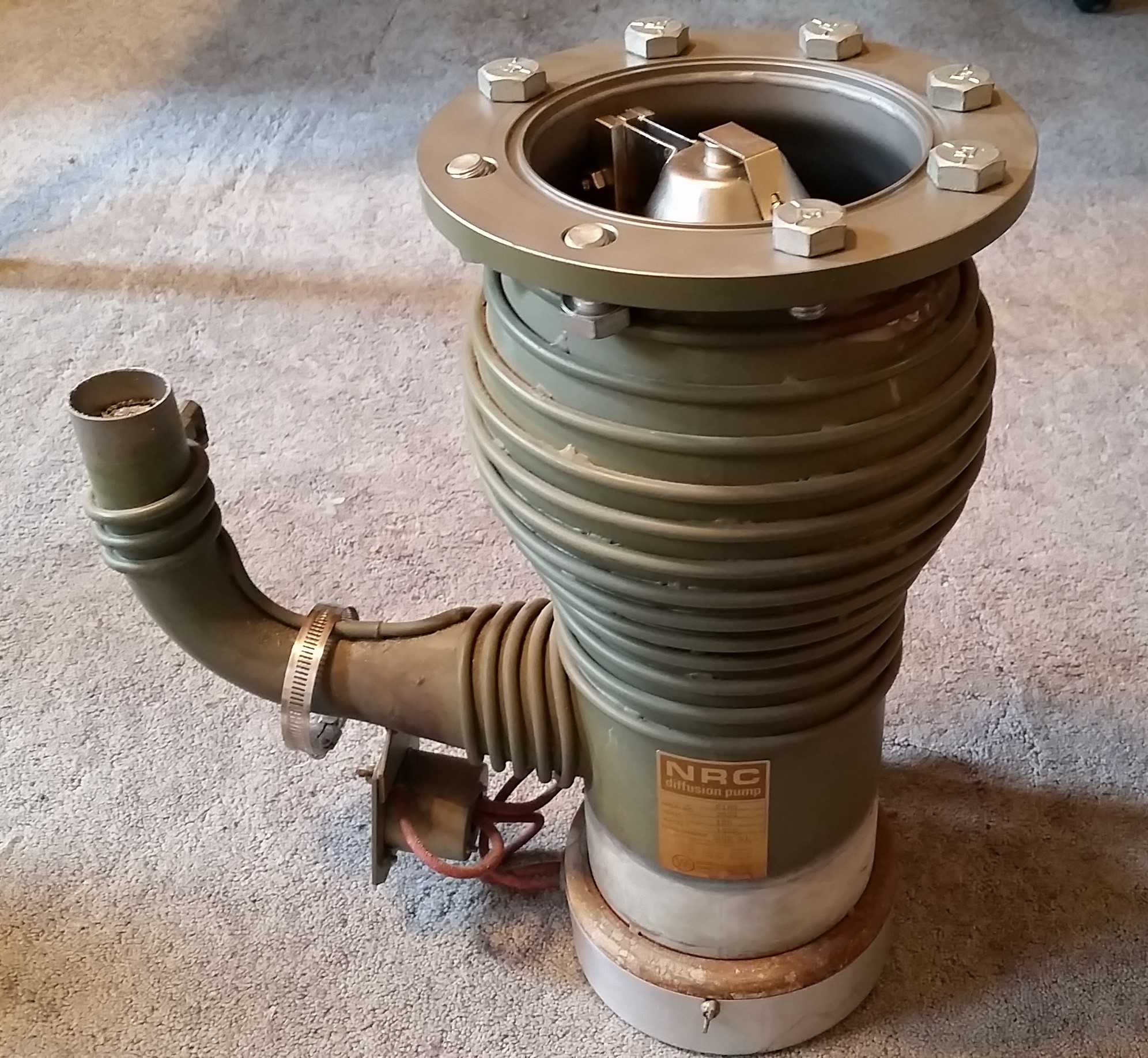
The main purpose of the cooling system is to provide cooling for the diffusion pumps used to pull high vacuum. Two diffusion pumps have been obtained in nearly new condition for experiments – an Edwards EO4, and a NRC 0183 (Varian VHS-4 equivalent). The Edwards pump is rated at 850W, while the NRC 0183 is rated for 1450W. Essentially, these pumps are large heaters that boil special oil which is internally directed and sprayed in a specific manner to create an extremely high compression ratio between the inlet and the outlet, thereby inducing a pressure difference and causing pumping action, to achieve high pumping speeds in the high and ultra-high vacuum regimes. In order for these pumps to work properly without overheating and burning the oil, causing catastrophic failure and system contamination, the pumps must be cooled. Water cooled diffusion pumps have a cooling line that wraps around the outside of the body in which coolant is flowed from the top to the bottom of the pump. In the case of these two pumps, as per manufacturer specifications, cooling should be no more than 25C at the outlet, with cooling ideally at 15C. This requires the use of a chiller system to not only handle the large heat load of these pumps, but to ideally bring the coolant level down below ambient before entering the pump cooling lines.

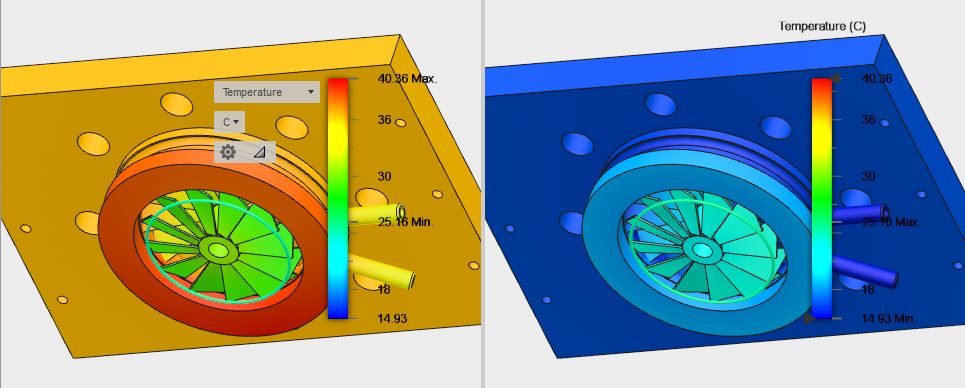
Several preliminary studies were completed to simulate the effects of cooling on the diffusion pump,as well as the adapter plates and water cooled baffle above the pump that helps reduce backstreaming from the oil. These simulations, done with the free CAD software Fusion 360, provided an initial look of what thermal behavior was to be expected during normal operation. These simulations will be verified during the qualification of the cooling system via thermal imaging. The study details and results can be found here:
-
Steady-State Static Thermal Analysis of the Edwards EO4 Diffusion Pump
-
Steady-State Thermal Analysis of an Optically Dense Water Cooled Baffle
III. SYSTEM PARAMETERS AND REQUIREMENTS
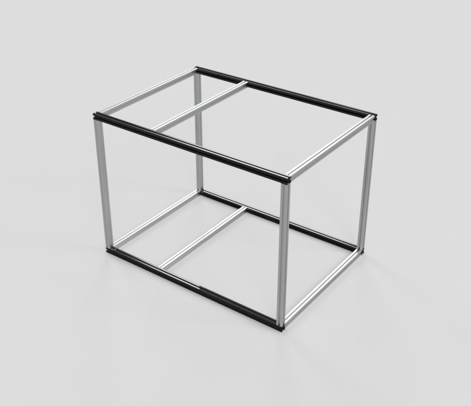
While there are many commercial system available that can accomplish this, they often run at a much higher price than is reasonable for an amateur budget. As a result, the cooling system was designed and built to exceed requirements while using both commonly available parts as well as being implemented as a low-cost and easy to make system. Form factor was also selected to mount within the space of the test stand, which measures at 2’x2’x3′:
The following requirements for the cooling system are summarized below:
- Low cost solution built with easy to obtain/replaceable parts
- Small form factor
- Modular design that could be changed based on user needs, as well as easily serviced
- Handle the heat load of either diffusion pump (850W or 1450W) with overhead
- Be able to chill the coolant to below ambient (ideally to 15C)
- Provide numerous sensory feedback for tight automated control and monitoring
- Closed loop design
- Form factor that fits within the test stand
- Have reasonable coolant tank capacity
- Have the ability to be upgraded and expanded in the future, with built in space and ports for these future system expansions
A basic cooling loop will consist of a few simple components – a storage tank, a thermal load, a coolant pump, and a heat exchanger to remove heat from the system. A very simple closed loop system could be used for the diffusion pump – using a sufficient heat exchanger, the coolant can be kept at ambient. While the pump could certainly run with cooling water temperatures at ambient (by ambient, I am referring to average room temperature), ideally the diffusion pump will run more optimally with reduced cooling temperatures. Also in consideration is the water cooled baffle that sits on top of the inlet of the pump to prevent backstreaming of the pumping oil into the main chamber. Generally, the colder the baffle is run, the more effective it is. Preliminary thermal simulations show however that with no cooling on the baffle, normal operation of the diffusion pump will result in some heating of the baffle.
The baffle and pump can either be run with parallel loops, or in series – often for water cooled baffles coolant is first run through the baffle then in series with the pump. Since the baffle is a significantly lower thermal load than the pump, it would be much easier to chill the baffle. However, while the initial plan was to implement a smaller separate chiller loop for the baffle, system planning and budgeting indicated that for the current iteration, the cost would be too high. Therefore, the baffle would be run in a fairly typical series configuration with the diffusion pump.
IV. METHODS FOR COOLING
As mentioned above, a key aspect of the cooling system is to not only handle the thermal load from the pump and the baffle, but to also chill the coolant below ambient. There are three main ways this could be accomplished –
- using an external source of cooled water, such as from a sink or faucet in an open-loop configuration
- using a refrigeration cycle compressor-based system
- using thermoelectric modules
Each method has advantages and disadvantages that should be taken into consideration. One of the major criteria is that the cooling system should be closed loop. While an open loop system running from a faucet would be dirt cheap, it relies on the setup always being near a source of running water, and is largely wasteful. A refrigeration cycle based system, like ones used in refrigerators, can be readily obtained and modified from a wide range of sources – mini-fridges, AC units, and other similar devices. These could be used to readily chill water based coolant, and depending on the size could handle quite large heat loads. However, the downside is that this would take up room, and is more bulky and would probably require the unit to be built as a stand-alone chiller (which could certainly be very advantageous for other equipment as well.) However, for the high vacuum test stand, I wanted a solution that integrated directly into the 80/20 stand, and take up minimal space. In this case, the stand would include the entire cooling system, in addition the the low vacuum, high vacuum, control modules, and low power systems needed, making it more portable and taking up less floor space. Thermoelectric coolers, based off of Peltier modules, could be implemented for this purpose. However, Peltier coolers are rather inefficient, and require a great deal of planning to handle reasonable heat loads. While Peltiers are quite cheap now on eBay, a system built from the ground up can still add up in cost and complexity, and will have much lower cooling capacity for an equivalent power input when compared with compressor based refrigeration cycles. Although it is the least efficient method, potentially the overall most costly, and very challenging to build from the ground-up with less heat-load handling potential, based on my space requirements and desire to build an all-in-one test stand, I decided to opt for a Peltier based chiller system.
V. TOPOLOGY
Now that the method of chilling the coolant was selected, the system topology needed to be decided upon. This could range anywhere from a very simple single-loop system to more complex multi-loop systems. While a single loop system is the most cost effective (with all elements in the loop in series), due to the lower heat load handling capability of the peltiers, and the rather high heat load presented by the diffusion pump, this would not be very feasible. While a large array of peltiers could be used to handle the load, it is not very efficient, and would require a rather large power budget. After discussing the problem with a close friend who is very knowledgeable in cooling systems, it was suggested to utilize a multi-loop topology. While more complex and costly, it has several key advantages:
- Temperature of the loop can be very accurately adjusted and maintained, and depending on the design, could be made to react very fast to changes in temperature.
- The full thermal load from the pump is no longer required to be handled by the peltier modules alone, significantly reducing power requirements, number of peltiers, and loading on the peltiers.
It was decided to run the system as a triple loop, closed loop system. The primary loop consists of the water cooled baffle, the diffusion pump, and the primary heat exchanger in series, with a pump circulating coolant from the storage tank through the loop. The second loop would be run in parallel with the primary loop, consisting purely of the coolant pump and the peltier chiller module. In this way, coolant would constantly be cycled through the chiller at the same time as the main loop, and the incoming coolant from both loops would be re-mixed together in the tank, providing a balanced average temperature. Since the primary heat exchanger, in theory, should remove all of the bulk heat generated from the diffusion pump, the peltier chiller would only have to work against ambient, significantly reducing its engineering requirements. The third loop of the system is used solely to cool the hot sides of the peltier chillers. Liquid cooling is much more effective than air cooling alone for peltier modules, and this would help handle the heat generated by the peltiers in the module and allow the system to operate at a temperature lower than ambient. This loop also has its own separate pump, which feeds coolant from a secondary storage tank, through the peltier hot side cooling blocks, and through the secondary heat exchanger, which is designated specifically for this loop. Therefore, the hot sides of the peltier chillers should only be at ambient during operation, allowing for the cold sides to operate at lower temperatures.
VI. SYSTEM V1 DESIGN
From the system topology selection and previously identified requirements, the cooling system design could officially start. The main components would need to include the following: water pumps, storage tanks, peltier chiller modules, heat exchangers, cooling fans, sensors, and a mounting plate.
The first components to be spec’d out were the cooling pumps. Low cost 12V pumps were needed, that allowed for plenty of flow and pressure. The flow rating for the diffusion pumps are around 0.5 GPM – however, all of the tubing and heat exchangers needed to be taken into account as well. After significant browsing on eBay, and comparing with other cooling loop requirements seen with performance computer systems, a pump was found that could provide flow rates of up to 5 GPM, with pressures up to 58 PSI, and a head fating of about 25′. The pumps were also discounted, and several were purchased.
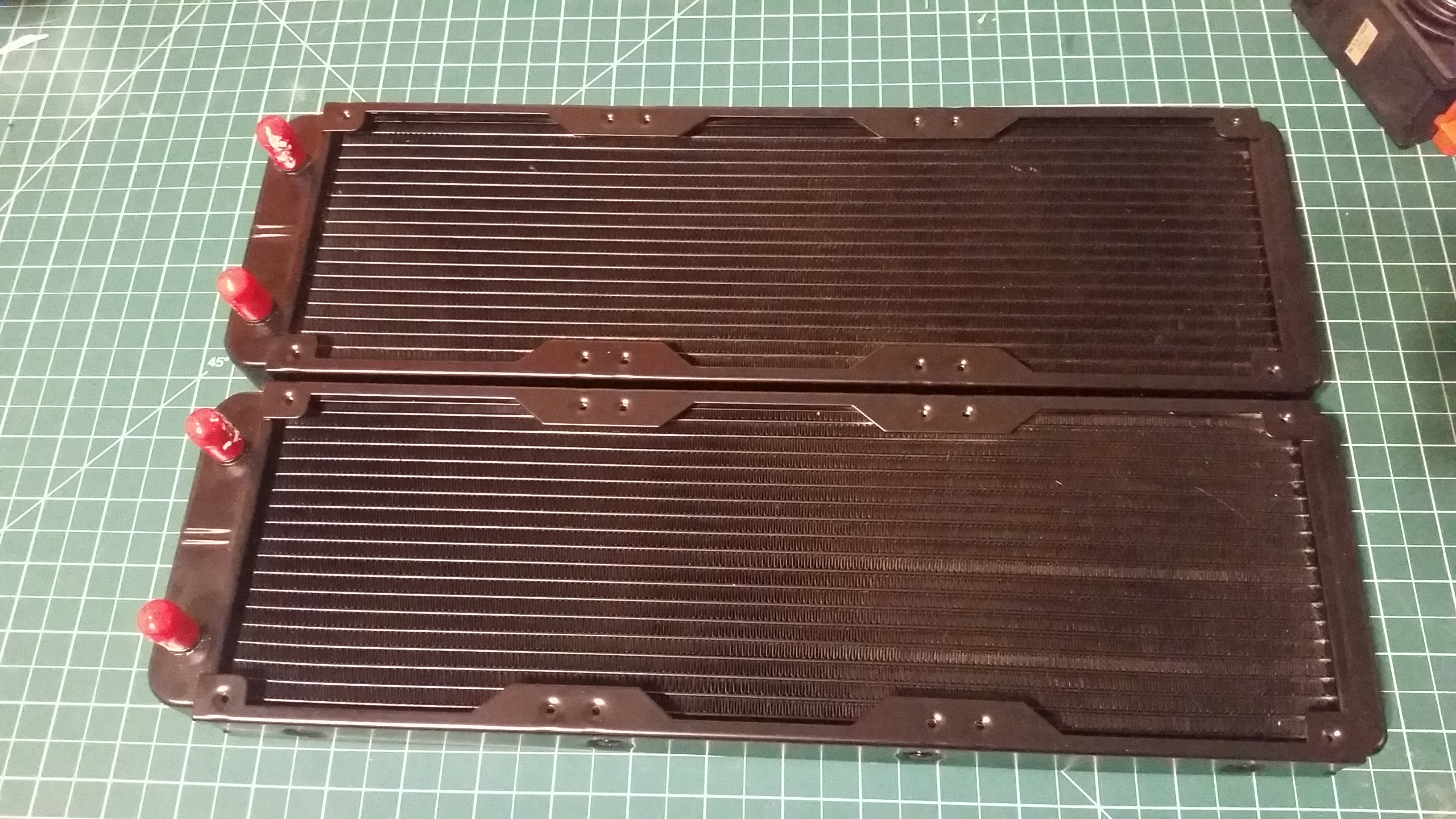
The next consideration was the heat exchangers. Originally for the V1 cooling system design, I had looked at examples from the performance PC cooling industry. Large three-fan PC cooling heat exchangers were selected, due to their low cost on eBay, and rating of up to 500W of cooling capacity each. It was decided to use up to two for the primary loop in series, with the provisions to add an additional two in the future, as well as using a single heat exchanger for the tertiary loop, while having provisions for adding an additional unit in the future. For cooling the heat sinks, high power fans scavenged from trashed servers would be used, saving cost since they were obtained for free and had high flow rates.
Next the cooling tanks were selected. My first initial thought for using relatively low cost and available materials was PVC. The operating temperature range of the coolant would be within PVC’s ratings, and it is very easy to find and work with. 4″ and 3″ diameter pipes were selected, which were also on-hand from previous projects, for the primary and secondary tanks, respectively. Brass NPT to barb hose fittings were selected for use as the hose connections to the tanks, which would be inserted into the appropriately tapped holes on the pipe caps. To make the tanks able to be disassembled for future cleaning or upgrading, rubber hose clamp based pipe adapters were used to create a tight, leak-proof jacket around the joints between the pipe and the caps without the need for using the more permanent PVC cement solution. The tanks would be mounted to the baseboard using hose clamps for ease of assembly.
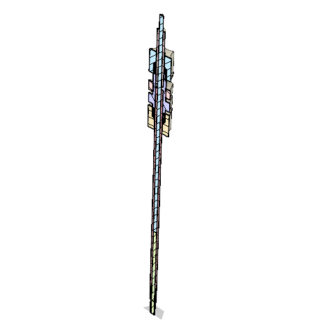
For monitoring the temperature of the coolant, small screw-in thermocouples were used. Since the housing rotated separately from the sensor itself however, they needed to be epoxy reinforced to prevent leaking. These sensors were mounted to the bottom of the tanks:
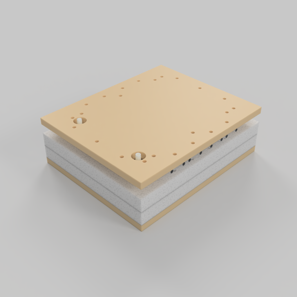
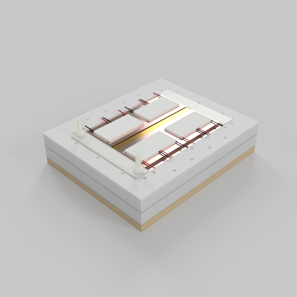
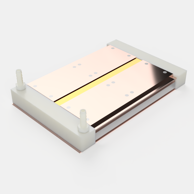
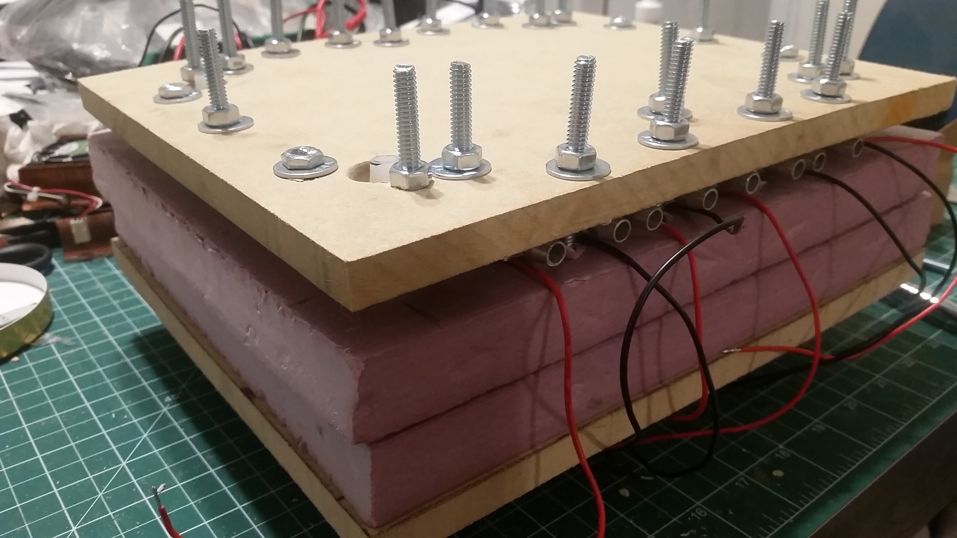
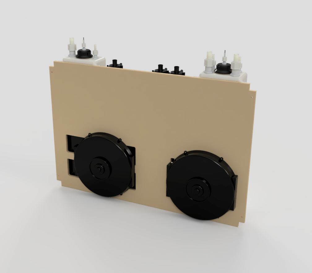
Finally, the peltier chiller module was designed. This consisted of peltier modules sandwiched between low-cost aluminum water cooling blocks – one set for the cold side, one set for the hot side. Five peltiers would be used for the module, for a total cooling capacity of about 200W at 12V input for a difference in 10C with the hot sides at ambient. The cold side would be further insulated with XPS insulation foam to reduce losses and improve cooling efficiency. The hot side would include three additional actively cooled copper heatsinks mounted to the top side of the aluminum block for initial heat extraction. The whole assembly would be sandwiched and bolted together between two sheets of plastic:

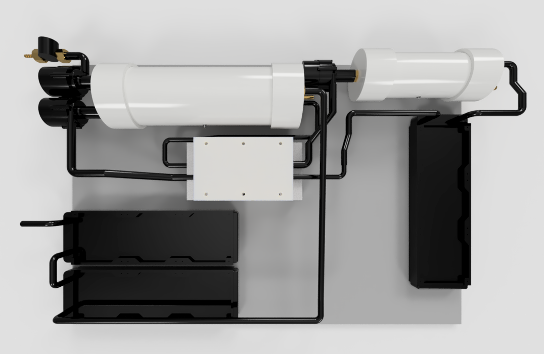
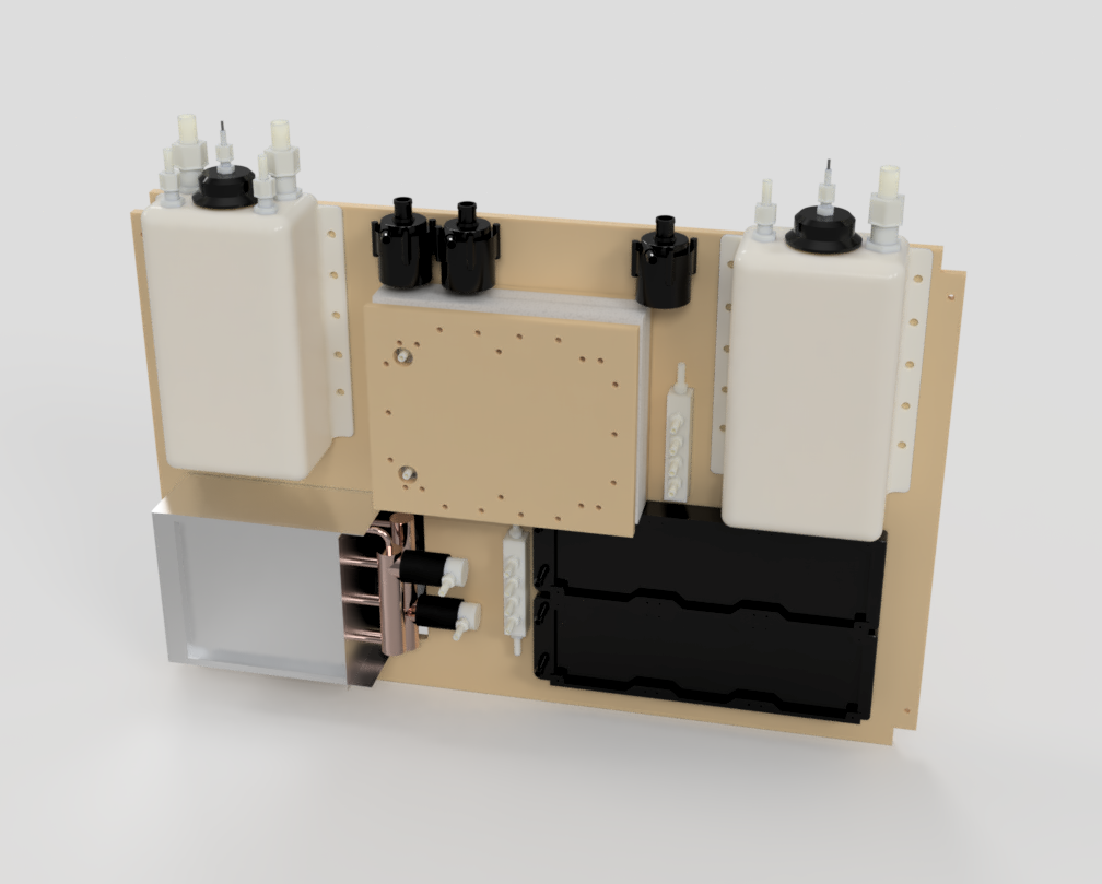
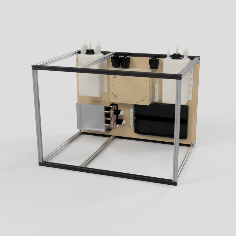
The final assembly would be mounted to a 0.5″ thick board of MDF, 2′ x 3′ to fit within the back plane of the 8020 test stand. For reference, below are the CAD renders of the finished V1 cooling system design (left), and the system mounted to the table with the small scale multipurpose V4 vacuum system (right):

VII. SYSTEM V1 FLAWS AND OVERSIGHTS
After additional further research into cooling systems, and having already built the storage tanks, I came to the realization that I did not account for the difference in metals in the cooling loop, which contained aluminum, brass, copper, and stainless steel. While brass, copper, and stainless steel are relatively compatible, aluminum was not, which would pose a severe galvanic corrosion issue if pure water was used. As a result, I first looked towards using some sort of corrosion inhibitor with the water to prevent issues. After much searching, the most common and best option was a glycol-based additive, commonly used with many different types of cooling systems, from PCs to cars (although with different additives depending on the application.) However, in my research into glycol based coolant, I stumbled across the fact that glycol is not chemically compatible with PVC, and will actually degrade it over time.
While the cooling tanks could be replaced, the fact remained that aluminum would be present in the cooling system with other incompatible metals. Although inhibited glycols exist for heavily mixed metals, such as in automotive applications, the more aggressive additives may impose a detriment with the thin channels in the aluminum heat exchangers. After more research and thinking, it was decided to scrap the entire cooling system design, and start over from scratch. This would also allow me to simultaneously upgrade the thermal load handling capacity of the system as well, which would need to be upgraded to run the larger NRC diffusion pump. In addition, after more consideration and review, it was decided that the peltier module would still be rather limited in capacity, and needed significant redesign as well. The design had minimal thermal mass, and the coolant would make very few passes through the cooling block, minimizing the time it spends getting cooled by the peltiers. The peltier chiller module, while it may suffice for very small loads, just didn’t seem large enough to handle the extra upgraded capacity, and probably the original capacity as well. This would mean the complete redesign of the peltier chiller as well to improve its cooling capacity. The cooling tanks, due to the awkward tube shape mounted to the baseboard, were relatively inefficient space-wise for the capacity it held. I opted to look for rectangular tanks to make better use of the space, and make it easier to mount while increasing the coolant capacity of the system as well.
In addition, initial testing of the thermocouples revealed that they were not in fact stainless steel as advertised, and started to rust within hours of being submerged in water for testing. This necessitated the redesign and upgrade of all of the thermocouples as well, to make them both waterproof and corrosion resistant.
As a result, the following requirements were added to the original list:
- Upgraded sensors for monitoring coolant temperature
- Full system corrosion resistance
- Have all materials (both metals AND plastics) fully chemically compatible with the coolant
- Provide significant cooling overhead for series operation of the baffle and diffusion pump, as well as additional cooling needs for other future systems
- Higher thermal load capacity for the peltier chiller module
- Higher capacity coolant tanks
VIII. SYSTEM V2 DESIGN
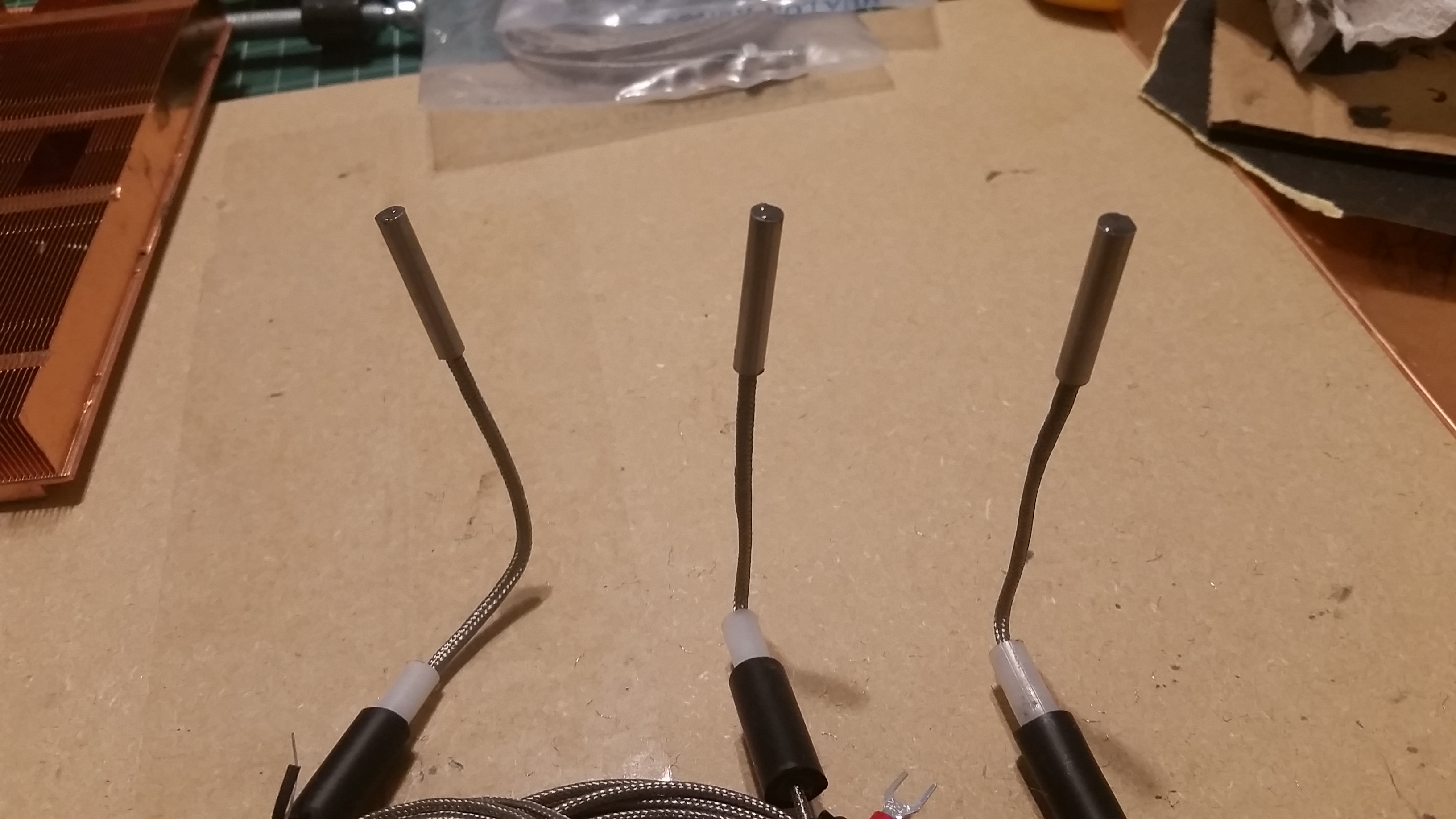
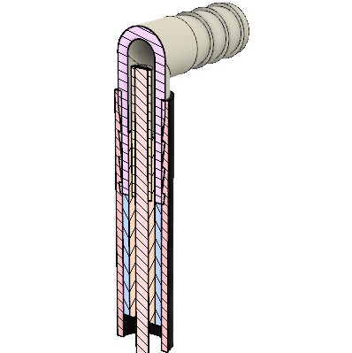
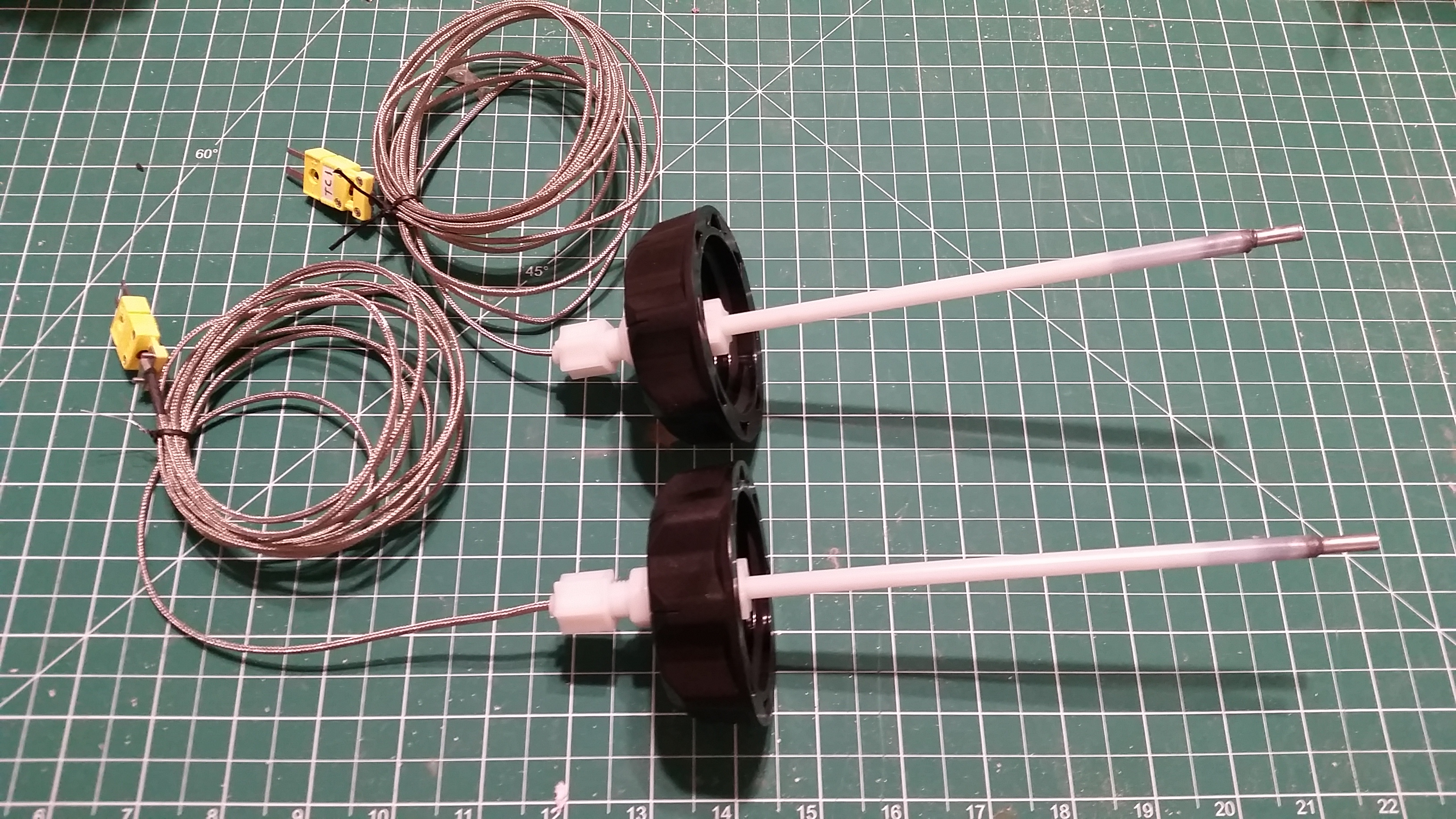
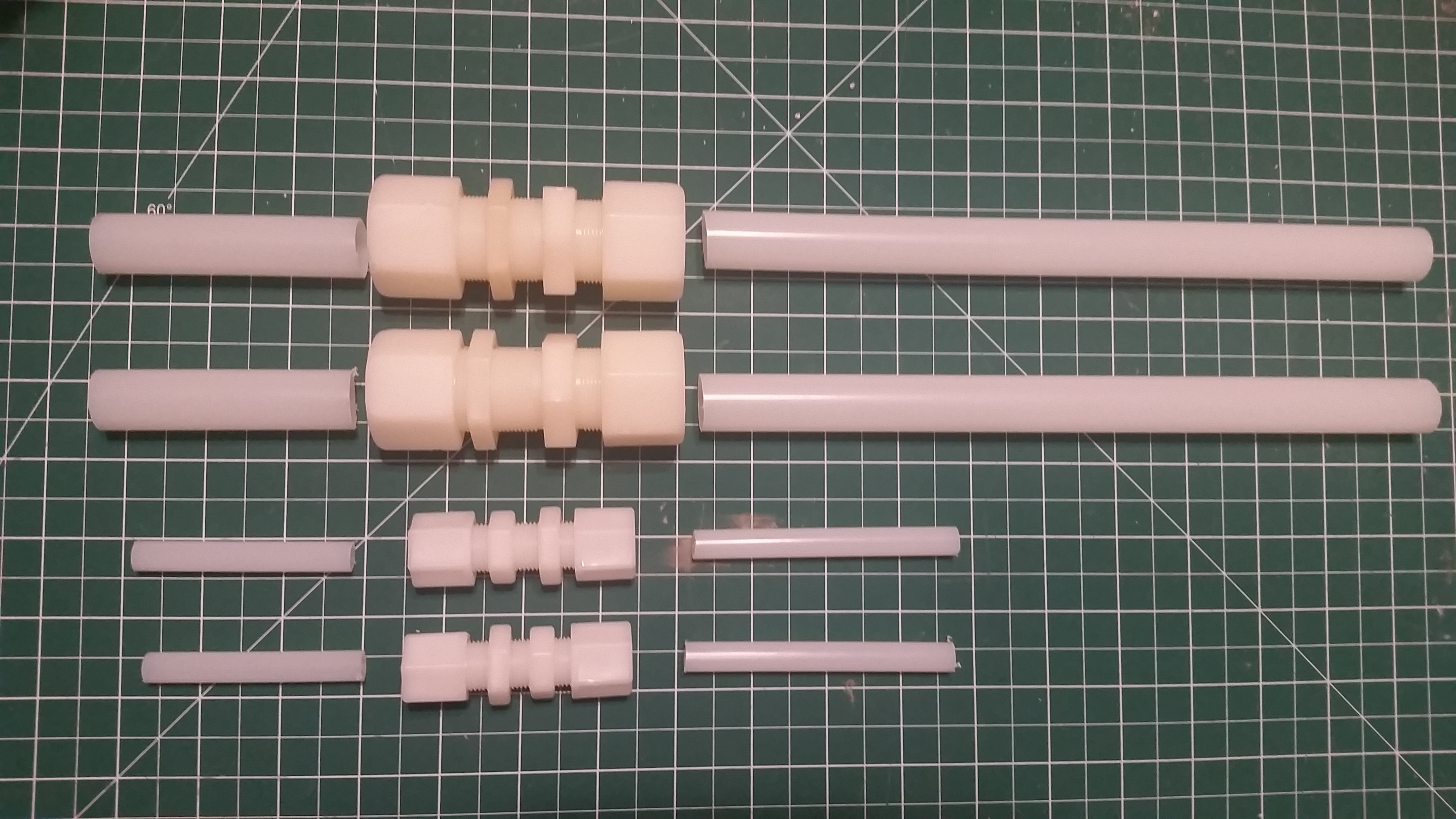
The very first thing that needed to be done was to upgrade the thermocouple sensors. It turns out that the cheap eBay thermocouples were not stainless steel at all, and were poorly made. There were two options: purchase new ones, or upgrade the current thermocouples I already bought. The outer casing on the thermocouples ended up being very easily removable, and allowed for easy modification. It was decided to create a new casing with actual 316 stainless steel, epoxied in place over the thermocouple junction. In addition, two types of thermocouple adapter probes were made: four probes that would be placed within the flow of the cooling lines, and two probes that would be mounted in the cooling tanks, at the center of the tanks for better average temperature readings. In addition, the original crimped fork connectors were replaced with high quality matched metal K-type thermocouple plugs, for interfacing with a custom thermocouple amplifier board. The complete build can be found on the Low Cost Thermocouple Rebuild and Upgrade page.

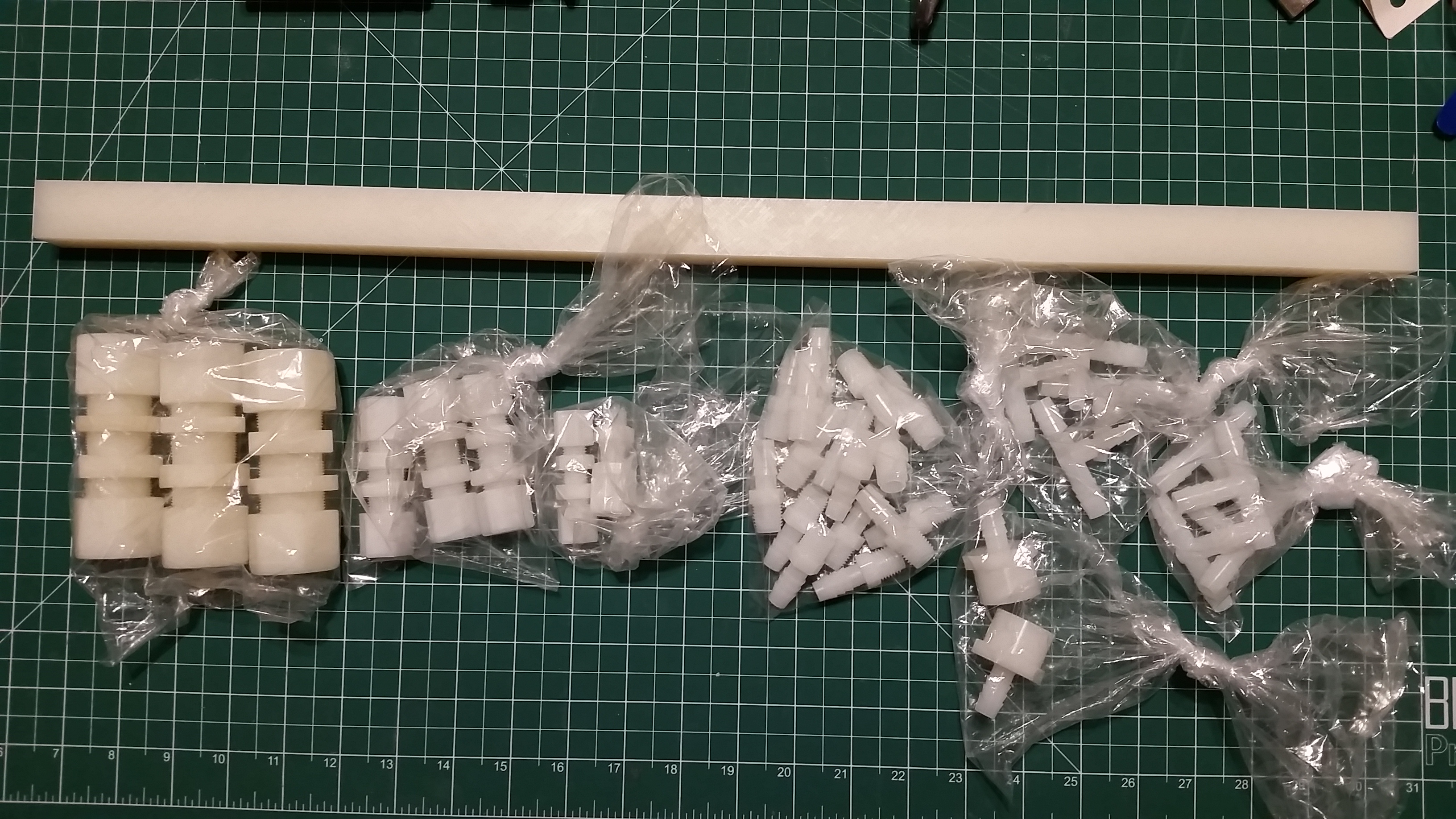
The first change to the V1 design was eliminating aluminum from the primary loop, which included stainless steel, copper, and brass. Since the tertiary loop used all aluminum heat sink blocks for cooling the peltier hot sides, the aluminum heat exchangers I planned on using could just be implemented in that loop. Being isolated from the primary and secondary loops, and having only one metal, corrosion in this loop would be eliminated. In addition, it was decided to switch from all brass NPT to hose fittings to solid plastic fittings – nylon was selected due to its low cost, very wide temperature range, and resistance to glycols.
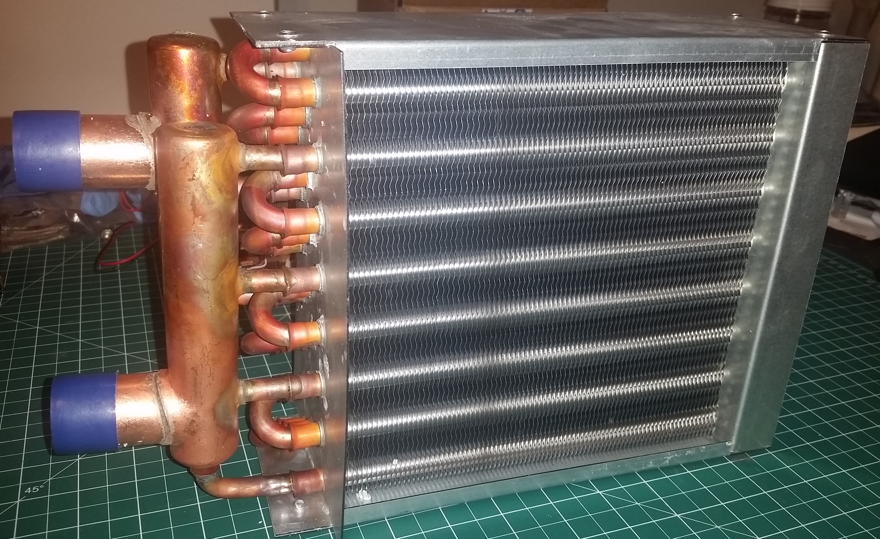
Next, since the primary loop heat exchanger had to be eliminated, a new one was needed. Fortunately a quick search on eBay yielded a large number of low cost solid-copper tubing based heat exchangers, normally used for furnace systems. The heat exchanger selected, with a small footprint of only 8″x9″, and a heat load capacity of 7kW for 500CFM of airflow, was an ideal choice. Not only would this heat exchanger reduce corrosion, it massively increase the heat handling capacity of the primary loop, and would work for either of the diffusion pump (technically both simultaneously as well without issue!)
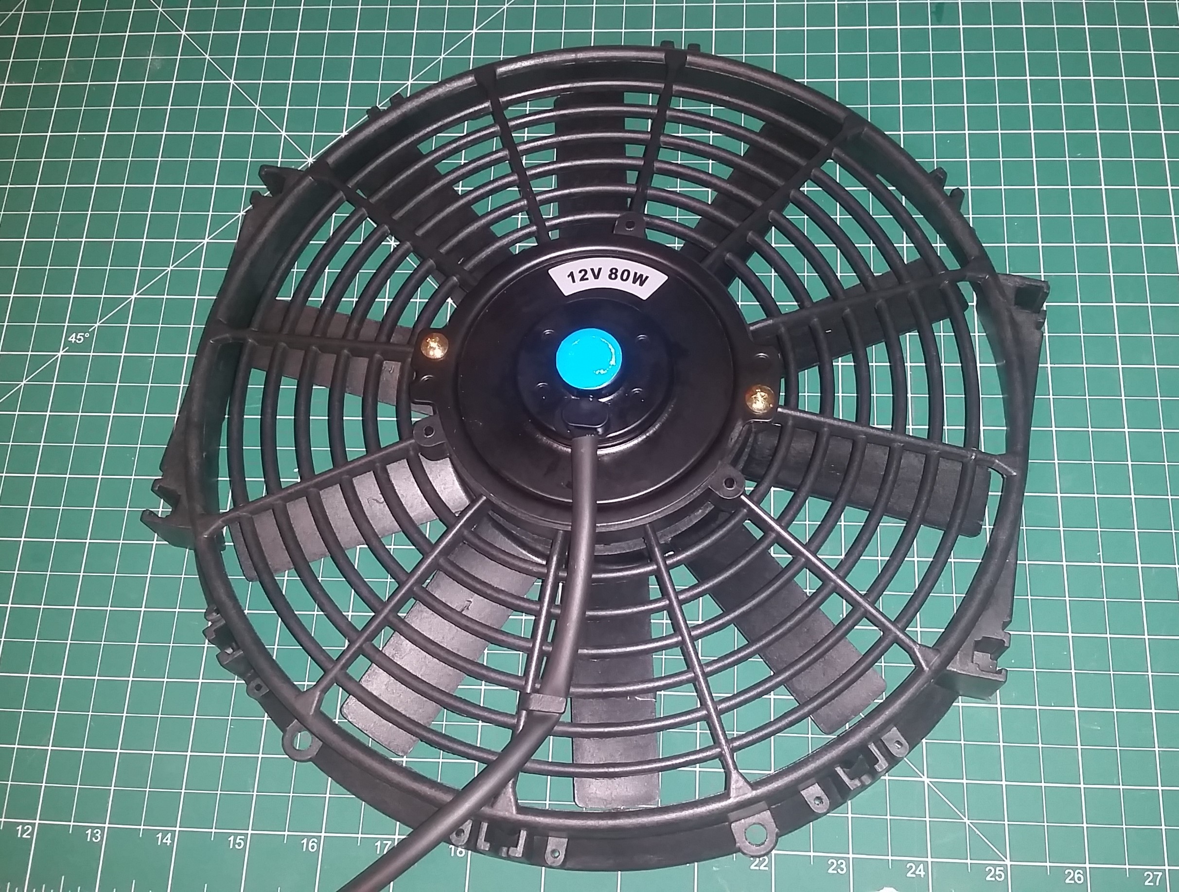
To simplify cooling the heat exchangers, instead of utilizing a large amount of small fans, two large fans would be used to cool each of the exchangers. Fortunately, high CFM fans used for car radiator cooling are widely available on eBay for very cheap. Two of these units were selected to cool the heat exchangers, with a rating of 1750 CFM. Since the fans are also 12V DC, the power requirements for running them would not change.
For the secondary heat exchanger in the tertiary loop of the system, since it was decided to reuse the aluminum cooling blocks for the peltier chiller hot side, the original aluminum heat exchangers could also be salvaged. Therefore, the entire tertiary loop would consist of only aluminum metal, as well as nylon, EPDM, and HDPE plastic, and being isolated from the primary and secondary loops, galvanic corrosion would no longer be an issue.
Because the secondary loop originally also used aluminum heat exchanger blocks, which ran in parallel with the primary loop, a new peltier cold side heat exchanger needed to be designed. Of all the parts of the cooling system, this is not only the most crucial for reducing the coolant to below ambient, but the most complex, and would need to be custom made, and needed to be made on as low a budget as possible. My first initial thought was to somehow modify copper heatsinks scavenged from servers to be used for this purpose. Drilling channels in the blocks, as well as brazing copper cooling tubes to the blocks were considered. However, a more unique and potentially more effective method was chosen, with less need for machining or brazing. By using the fins from the heat sinks themselves, which make up a very large surface area, significant cooling could be transferred from the blocks to the coolant if the coolant was somehow immersed in the fins. To reduce manufacturing complexity, it was decided to simply epoxy a backing plate made of copper to the fins with JB Weld, and epoxy end blocks to the open sides, with channels drilled into them to allow coolant to enter and exit through the fins. Instead of just immersing the fins in a tub of coolant, by offsetting holes, the coolant could be made to flow in series snaking through the fins, increasing transit time in the chilled environment, and hopefully improving cooling ability. While making the end blocks from copper would make the overall system more efficient, a cheaper and easier to manufacture solution would be to use solid nylon blocks. For a more thermally efficient design, at a higher cost and manufacturing skill requirement, brazing the entire assembly and using all solid copper would be the best solution. For now, the epoxied prototype with nylon end blocks would suffice. Full details of the peltier chiller build can be found on the Peltier Chiller Module build page.

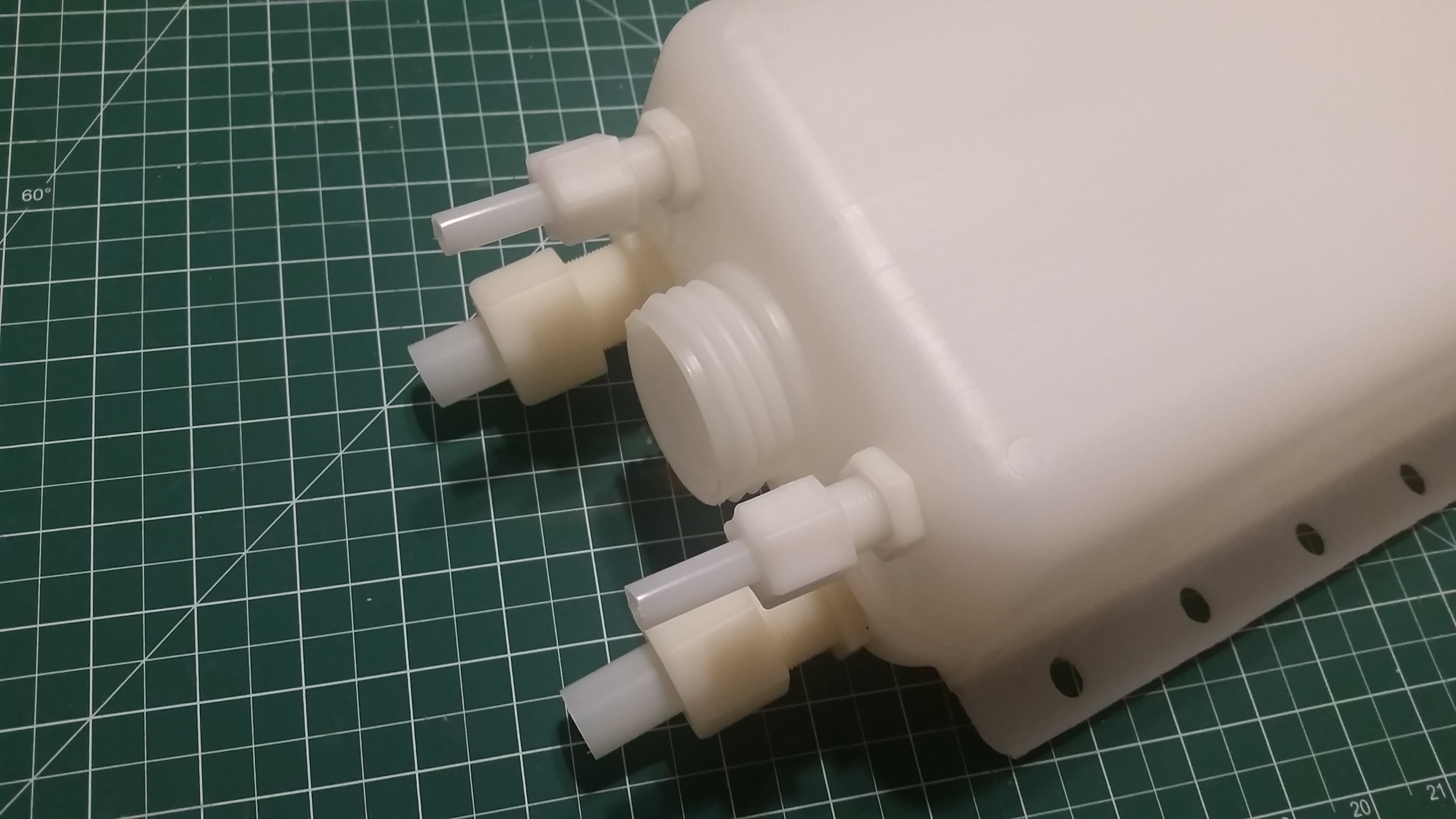
The next change to the V1 design was the coolant tanks. Since the primary loop would still have some stainless steel components as well as copper, while much more compatible than aluminum, an inhibited glycol-based coolant would still be preferred. As a result, the cooling tanks needed to be chemically compatible with glycol (either ethylene or propylene). High enough concentrations of glycol also help act as a growth inhibitor for algae as well. After some searching, I came across several suppliers of HDPE tanks, which are not only chemically compatible with glycols and many other chemicals, but widely available and relatively cheap. A rectangular tank would also be much easier to mount than the original cylindrical pvc tanks, and be more space-effective.
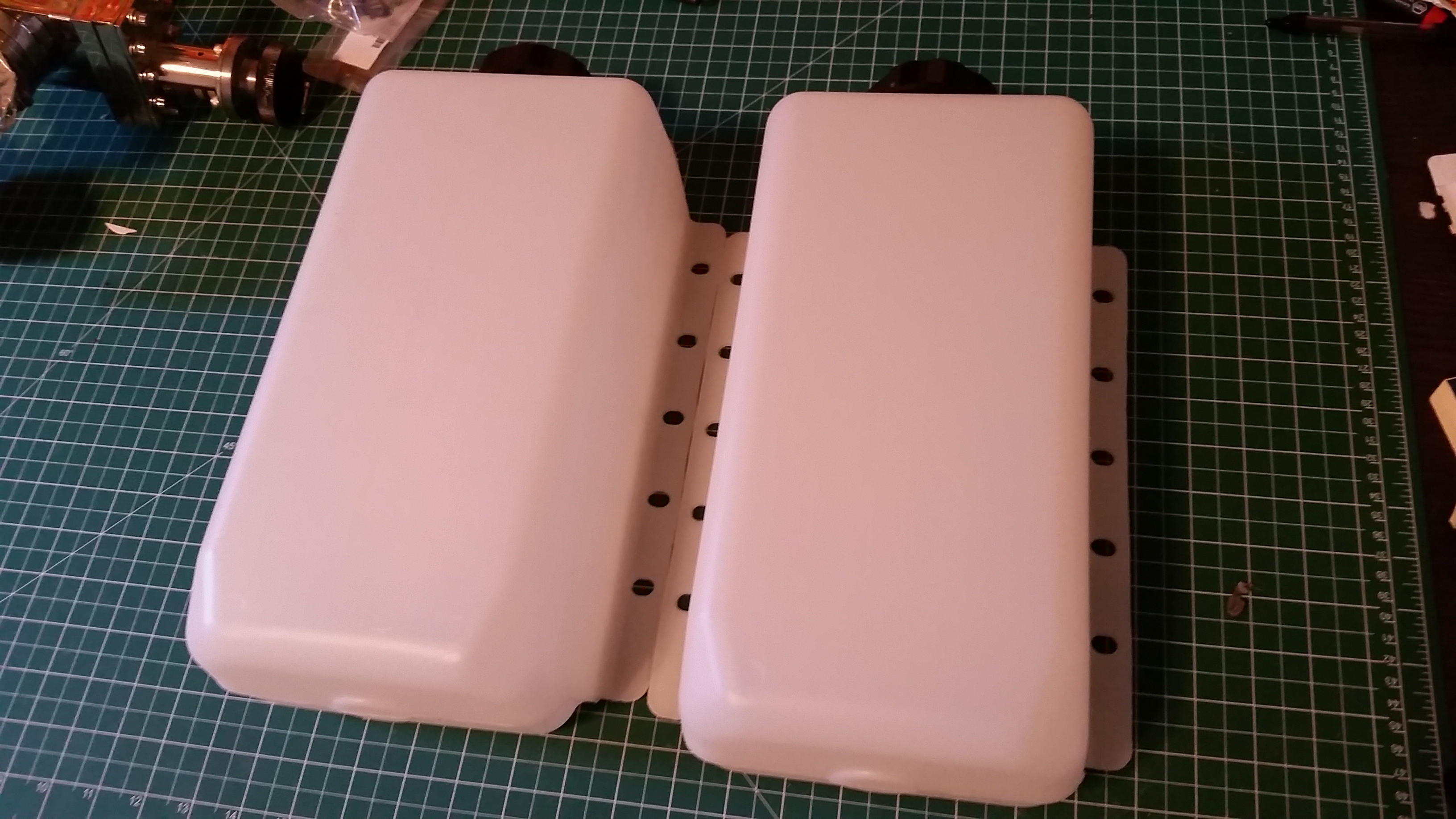
The new tanks would also allow for easier mounting of the inlets and outlets for the coolant. Utilizing nylon tubing and nylon Jaco bulkhead fittings, sized appropriate for the pumping and return lines used with the coolant pumps, the tanks were upgraded as well. In addition, the removable cap allowed very easy access to filling, and provided a perfect spot to mount the upgraded thermocouple probe adapters:
The final system would still be mounted on the same sized MDF baseboard. A downside still to MDF baseboard is that if it gets wet do to a major leak, it could fall apart. Marine grade MDF, or ideally, plastic sheet should be used. However, due to my tight budget with the project, and having already wasted enough money on the failed V1 design, it was decided to stay with the original MDF board (and do extensive and thorough leak checking of the system prior to filling it with coolant!)
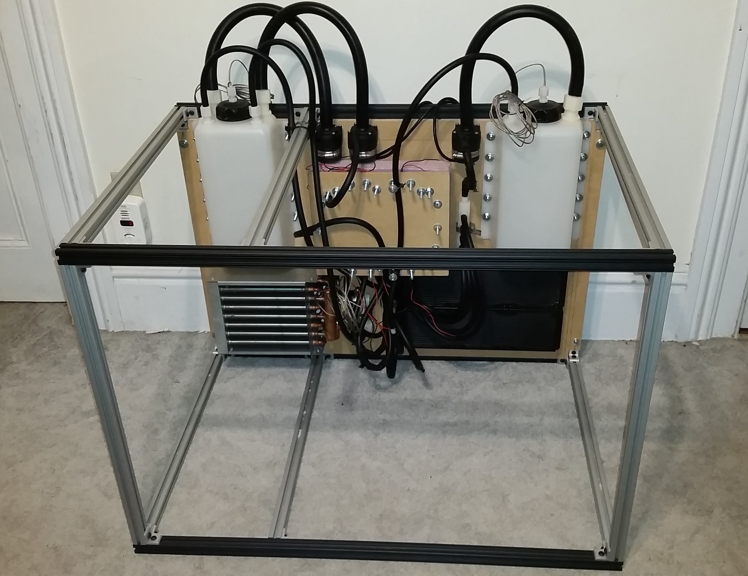
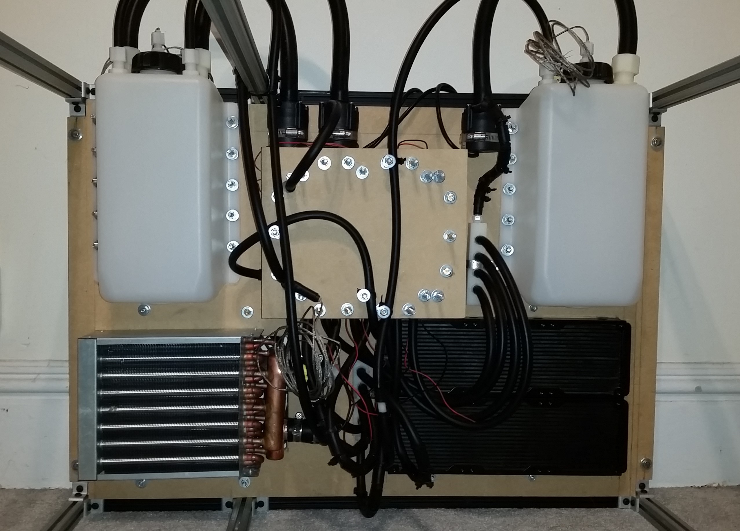
Finally, the cooling system was assembled, bolted to the baseboard, attached to the 8020 test stand, and the cooling lines routed:
IX. GOING FORWARD
The entire process, from the initial design sketches of V1, to the final tubing connection of V2, took several months to complete. It was a very challenging and difficult build, with many lessons learned along the way. Despite the extra time and cost of the rebuild, it has been well worth the effort. The system is now far better engineered than its previous iteration, and should be a great asset for upcoming high vacuum projects. However, the journey for this cooling system is not quite done yet. The system is physically built, but the electronics must now be wired, and the control system programmed for automated cooling cycle control, as well as providing real-time monitoring and data plotting of the temperatures of the system. In addition, the system will undergo full thermal imaging to diagnose just how well it works, and the sensors need to be calibrated to the coolant. Check back for the next installment were we explore the thermal imaging of the system during operation and qualification of the system!
X. SYSTEM BUILDS AND RELATED RESOURCES
-
Closed-Loop Peltier Water Chiller for Diffusion Pump Cooling Technical Overview
-
Closed Loop Peltier Chilled Diffusion Pump Cooling System Build Pictures
-
Peltier Chiller Module Technical Overview
-
Peltier Chiller Module Build Pictures
-
Lost Cost Thermocouple Rebuild and Upgrade Technical Overview
-
Low Cost Thermocouple Rebuild and Upgrade Build Pictures