After a long hiatus from physical system construction, having spent the past couple of months working on project planning and documentation, CAD modeling, thermal simulations, and plasma simulations, progress was made in the beginning main assembly of the Small Scale Multipurpose High Vacuum System V4. Details of the V4 system design can be found on the V4 project page:
Small Scale Multipurpose High Vacuum System V4 Design
During this build, the main chamber, high vacuum isolation valve, and high vacuum pipeline were cleaned and bolted together. Although this represents only a small fraction of the total system, it is nevertheless a critical, and exciting step forward towards experimental progress. For the assembly, all of the parts are layed out on an open, clean surface. The area that the main chamber components were assembled on was covered with a sheet of clean, plain, non-greased alumnum foil. It is a standard practice in high vacuum engineering to utilize clean aluminum foil for covering open ports, flanges, and assembling parts on, to help prevent any unnessesary contamination. The foil should be handled with clean, uncoated nitrile or similar gloves:
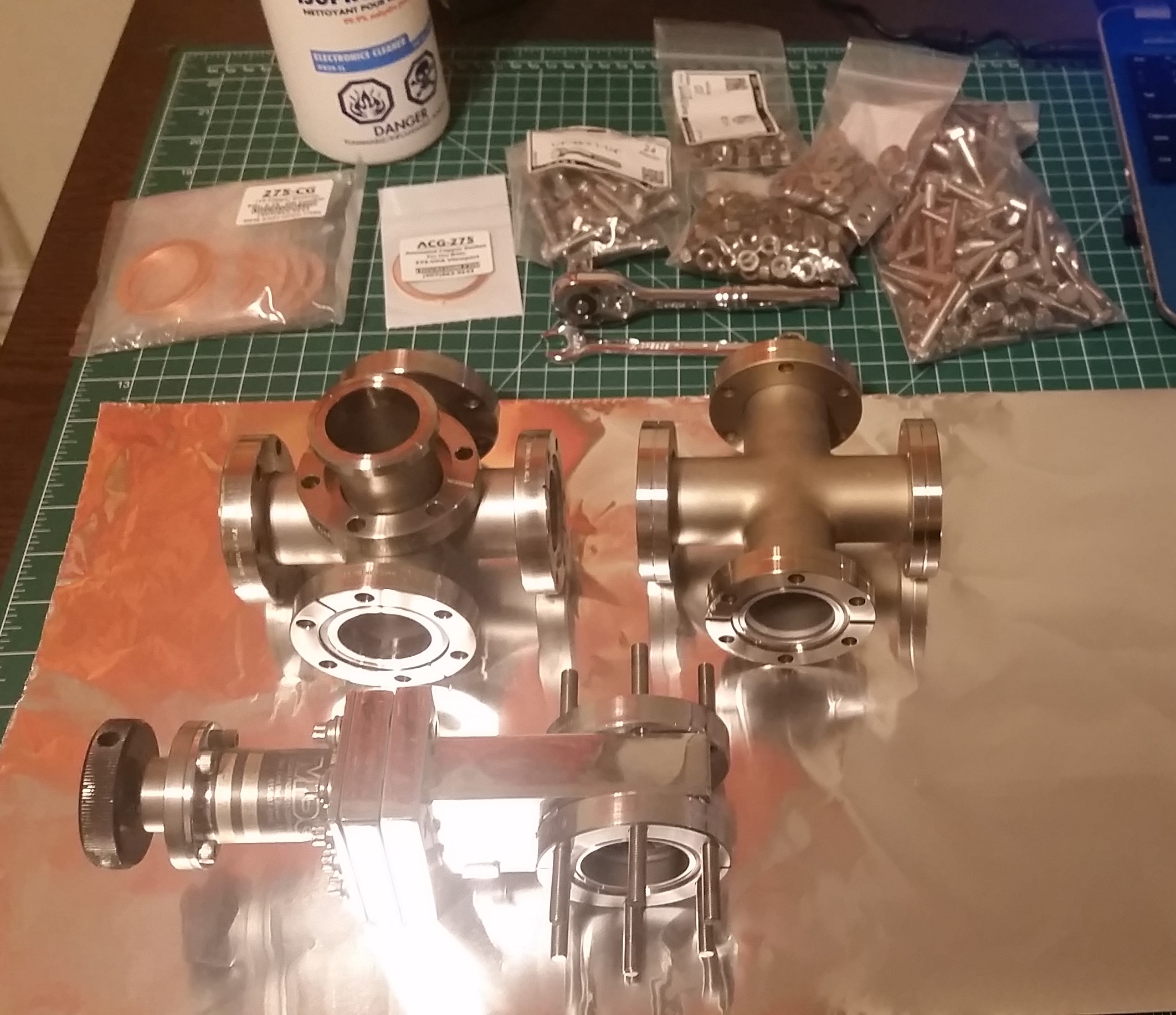
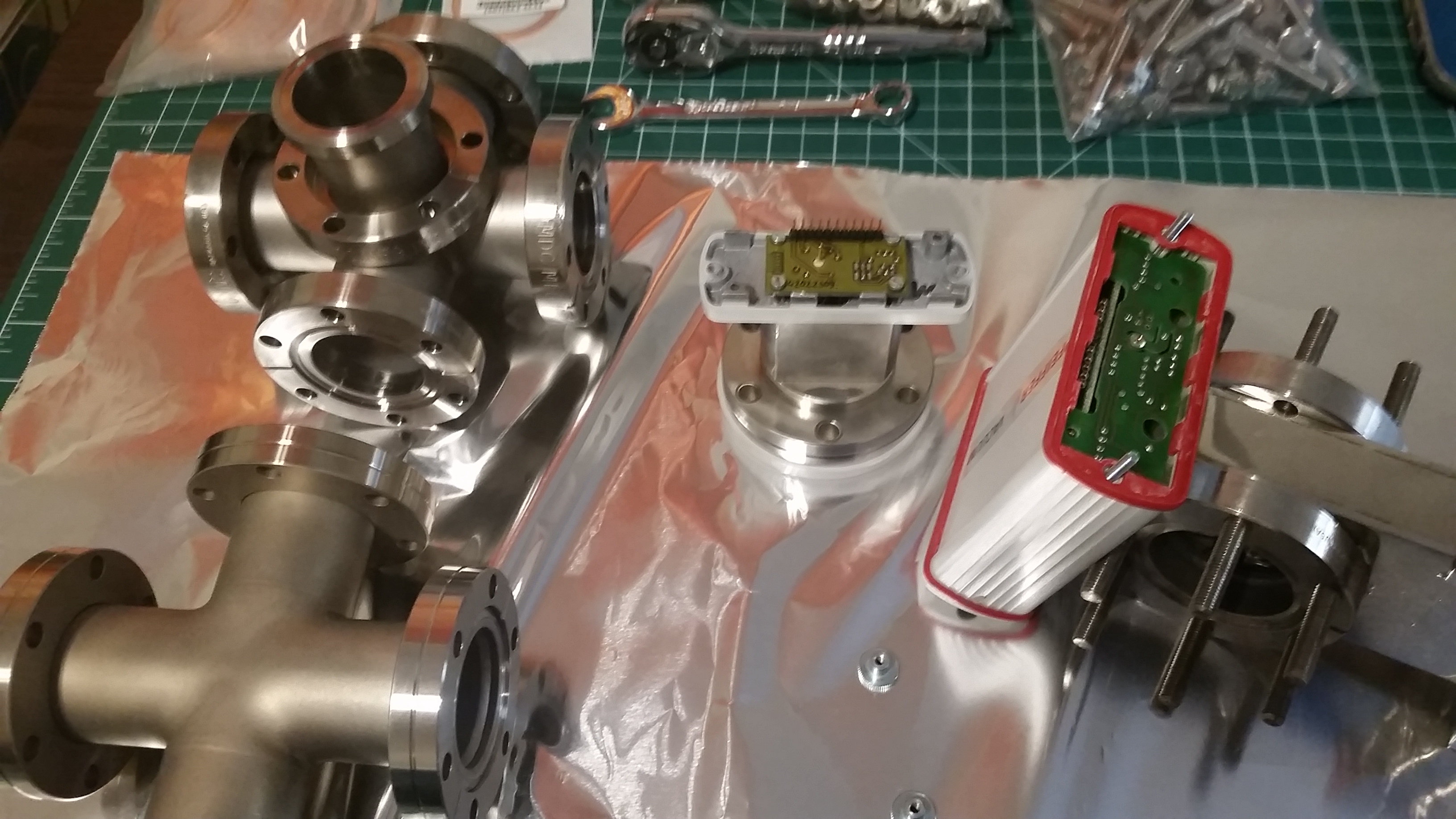
The main chamber consists of the five-way 2.75″ conflat cross shown in the above picture. This will allow for a viewport in the front, along with three additional inputs for various experiments. The four-way 2.75″ cross to the right of it is the high vacuum pipeline which connects from the adapter plate bolted to the diffusion pump. This was selected to minimize the vacuum pipeline length as much as possible to maximize pumping speed and conductance, while allowing for two additional ports for high vacuum instrumentation. Between the main chamber and the pipeline is a 2.75″ conflat manual gate valve. This is utilized to isolate the main chamber from the pipeline and diffusion pump. This will become more critical for later upgrades where ion pumps will be installed in a beam-line attached to the five-way cross to keep the chamber at a constant high-vacuum level with low energy consumption, as well as high vacuum experiments involving electron beams. Each of the components were carefully wiped down with 99.9% isopropyl alchol using Kimwipes and clean nitrile gloves.
The high vacuum gauge to be initially employed on the system is the Pfeiffer HPT-100 wide range high vacuum pressure transducer. Several of these were found in good condition used on eBay for only $40.00 each. Shown above, the main sensor head is separated from the control electronics for installation. When the system is baked for initial conditioning, the electronics must be removed to prevent damage from the heat of the bake-out, which is limited to about 150C due to the use of Viton o-rings in some locations.
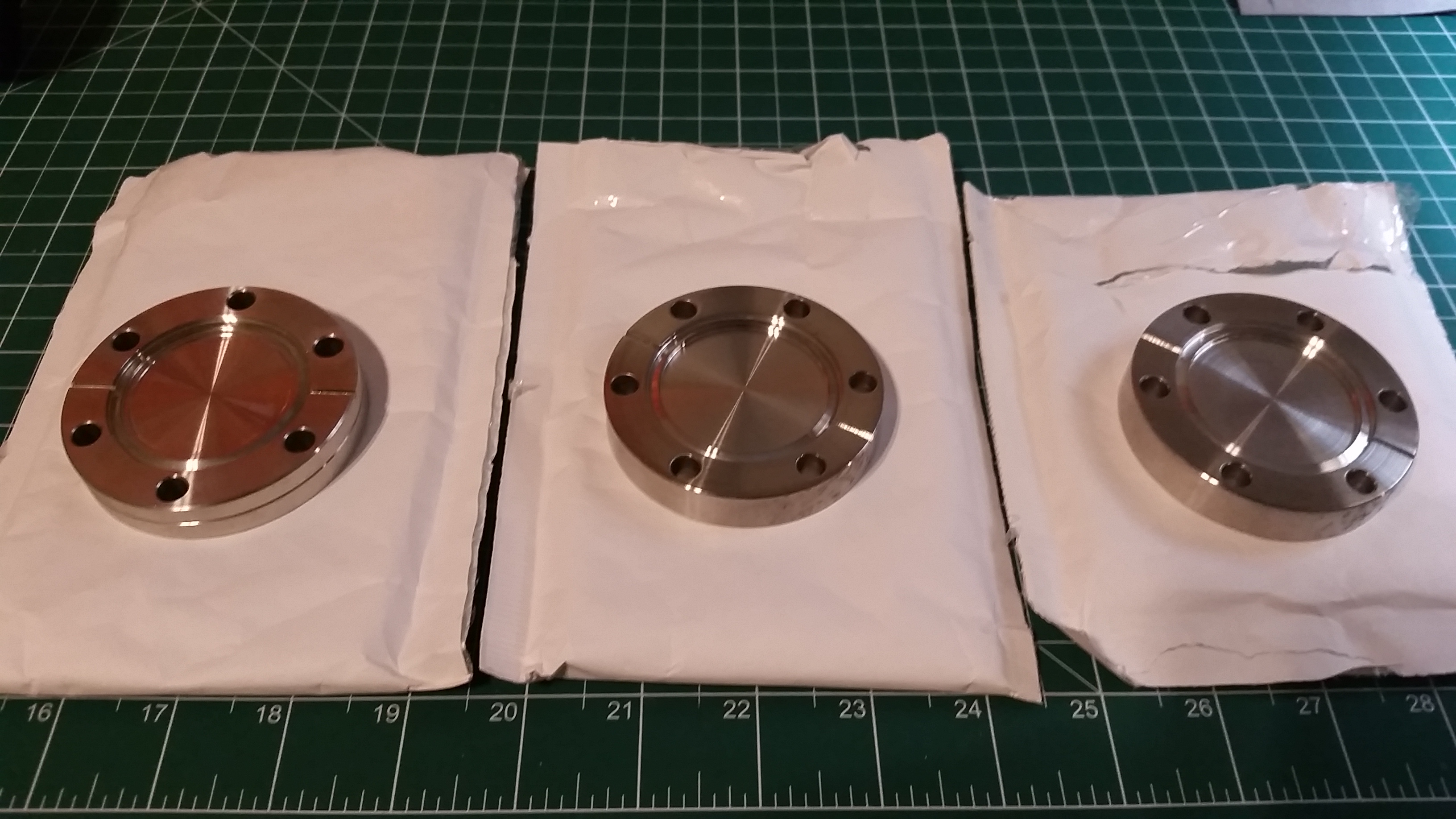
To cover the unused ports on the system during initial pumping, and while waiting for system upgrades, a set of 2.75″ conflat blanks are installed. These particular blanks were purchased as used surplus from BMI Surplus, but are in excellent condition, and were only $10.00 each:
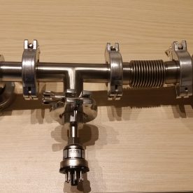
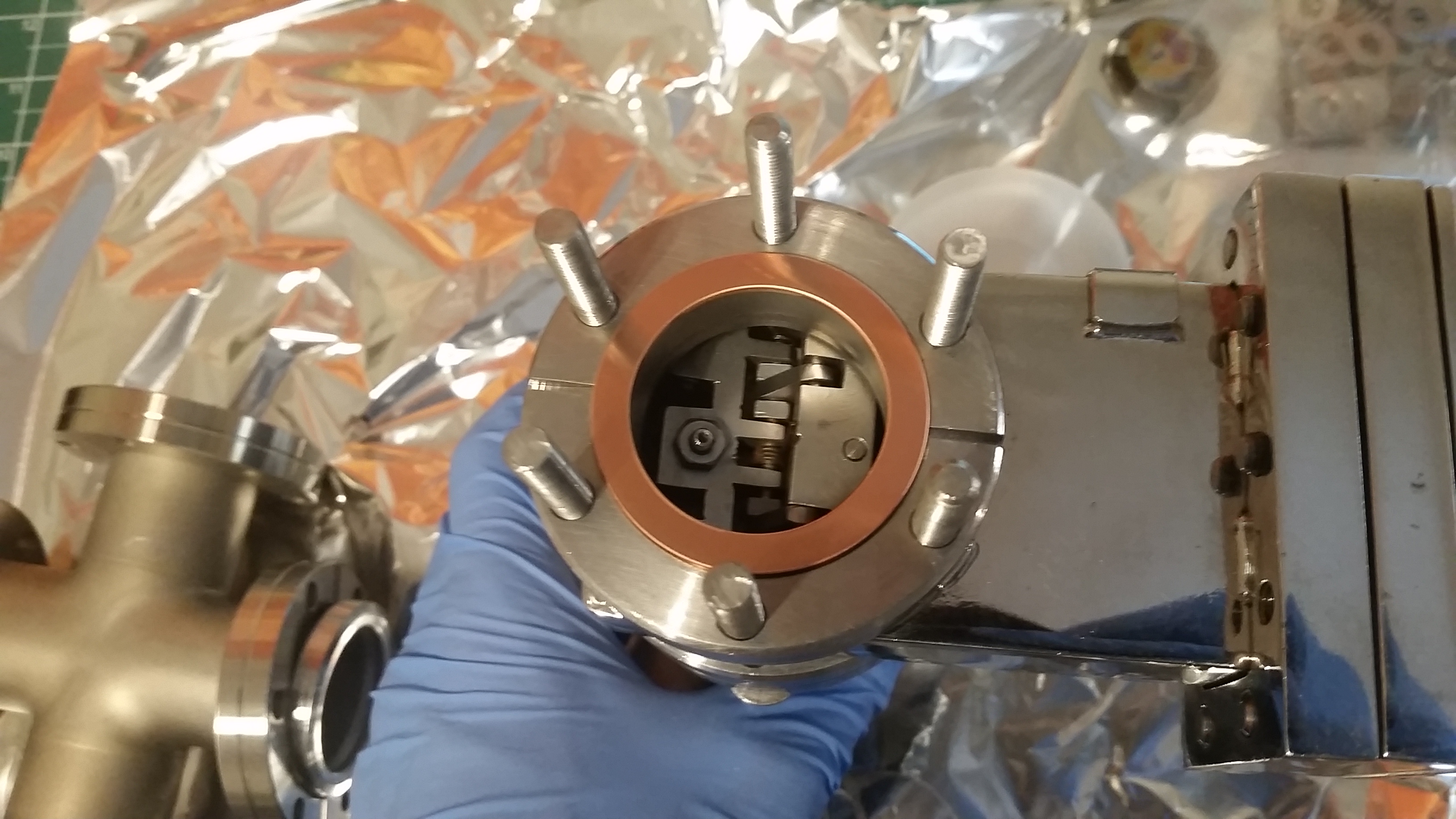
Here you can see a brand new, clean copper gasket being installed on the bottom portion of the gate-valve. Also a nice look into a bit of the mechanism for closing and sealing the valve – these are quite mechanically complex! This particular valve is an MDC GV-1500-M valve, rated up to 10^-11 Torr. This was obtained very fortunately for free through a parts trade.
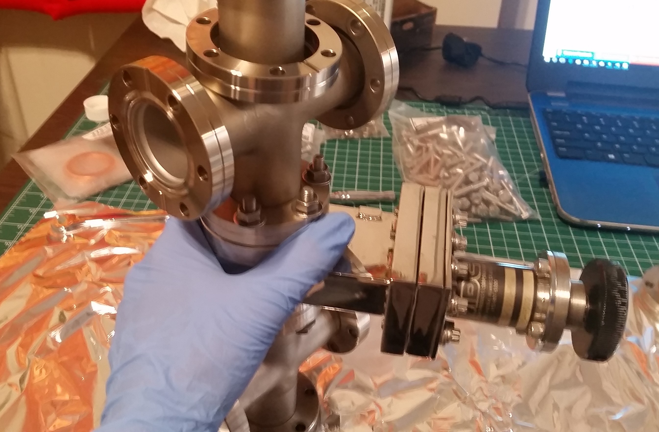
Next, the four-way cross is aligned and bolted to the bottom of the gate valve after the top chamber is secured:
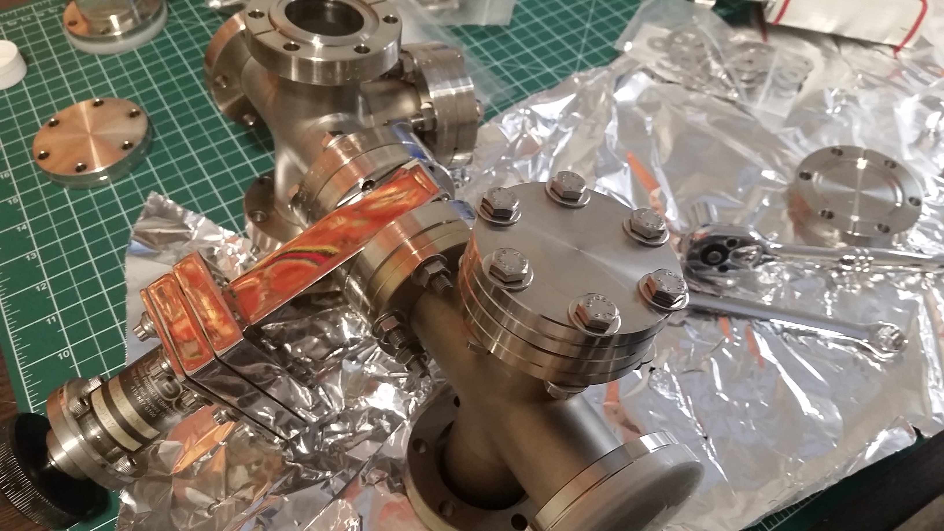
A couple of blanks are then mounted to unused ports:
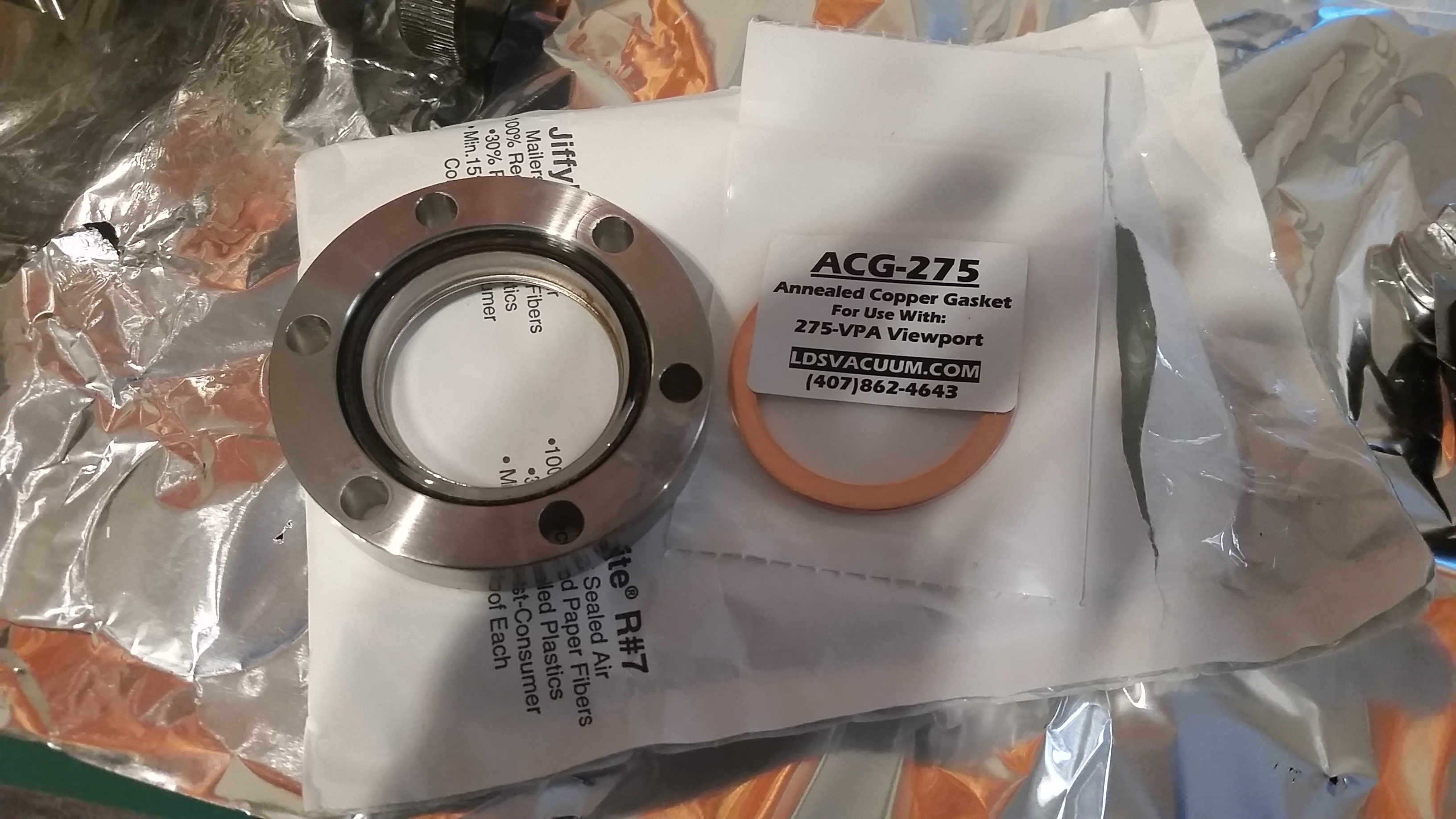
For experimental viewing of systems run in the main chamber, a 2.75″ conflat viewport is utilized in the front-facing port of the five-way high vacuum cross. This viewport was also purchased BMI Surplus for an excellent price of around $90.00, which lower than if purchased new, and is flawless condition. Unlike standard copper gaskets, for viewports, annealed copper gaskets are required, to prevent fractures in the viewport during bolting. The annealed copper gasket was purchased from LDS Vacuum, along with the other standard copper gaskets. Both BMI Surplus and LDS Vacuum are excellent sources for low-cost vacuum components.
Finally, the subsystem in its newly assembled state. Note that several of the ports are covered with aluminum foil – this is to prevent dust and contamination from entering the chamber. The other ports will have additional equipment mounted when ready.

For now, this subsystem is assembled as far as it can go. The next stages will be to machine the aluminum adapter plates, prepare the diffusion pump, create the system housing, and prepare the remaining instrumentation and feedthroughs for mounting on the remaining ports.
Sources for the above components are as follows:
- High Vacuum Crosses – eBay
- Pfeiffer HPT-100 High Vacuum Transducer – eBay
- 2.75″ Conflat Blanks – BMI Surplus
- 2.75″ Conflat Viewport – BMI Surplus
- 2.75″ Copper Gaskets – LDS Vacuum Shopper
- 1/4″-28 Stainless Steel bolts, nuts, and washers – Bolt Depot
Build pictures will be continuously updated as progress is made on the System V4 build photos page:
System V4 Build Pictures
You can also follow Applied Ion Systems build updates, photos, and other informational releases on the Applied Ion Systems Twitter and Instagram pages.