UPDATE – As of 10/15/2018, the presented thermal analysis study is outdated and obsolete. A new, more accurate, and updated simulation model and analysis can be found HERE.
OVERVIEW
This thermal analysis study is the second thermal analysis for the full system design of the Small Scale Multipurpose High Vacuum System V4 Design. The goal and purpose of the study is to build off of the prior study, Steady-State Static Thermal Analysis of the Edwards EO4 Diffusion Pump, to determine the steady state thermal characteristics of a selected water cooled baffle in operation with the entire diffusion pump and adapter plate configuration, for both uncooled and cooled baffle operation. This study also serves as the precursor for a future study that covers the design and analysis of the closed loop, multi-loop, chilled PID controlled cooling system for the baffle.
The thermal modeling results are based off the CAD and thermal modeling analysis using Fusion 360. Differences between the actual dynamic operation of the pump and the static modeling of the system is covered in the prior study, and estimates are given to best compensate for these differences to a good degree of accuracy and confidence level. The results also directly utilize the prior study setup and results to create the foundation for additional thermal loading modeled in the complete setup, as described below.
Thermal Analysis Study Results and Discussion
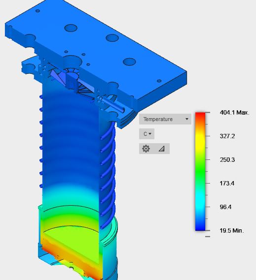
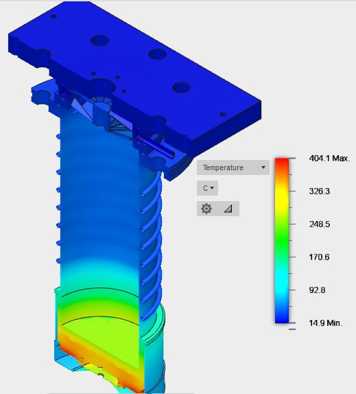
Figure 1 (Top Left): Full Model Cross-Sectional View, No Baffle Cooling. Figure 2 (Top Right): Full Model Cross-Sectional View, Baffle Cooling @15C
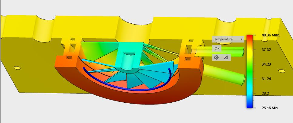
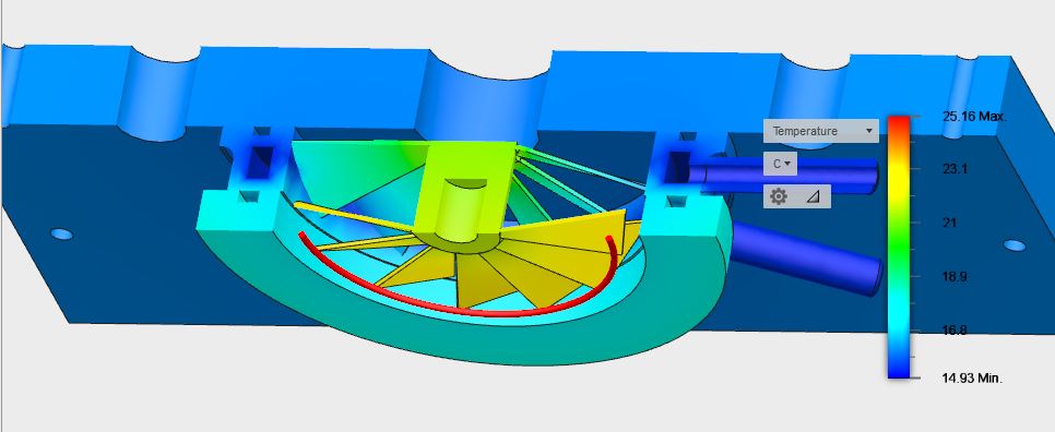
Figure 3 (Top Left): Water Cooled Baffle and Adapter Plates Cross-Sectional View, No Baffle Cooling. Figure 4 (Top Right): Water Cooled Baffle and Adapter Plates Cross-Sectional View, Baffle Cooling @15C
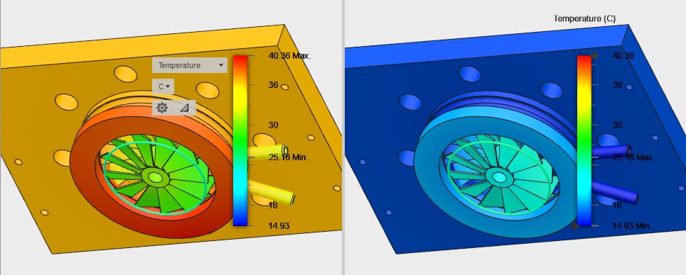
Figure 5 (Above): Uncooled vs. Water Cooled Baffle and Adapter Plates Full View, Normalized Temperature Scale Comparison
Summary:
The study sets up a comparison between two modes of operation for the baffle in the system: uncooled while the pump is running, and cooled to 15C while the pump is running. The cooling temperature of 15C is selected as the temperature for the baffle for this study as prior design criteria has identified it as the maximum inlet temperature the baffle should be operated at for effective backstreaming reduction into the ultra-high vacuum regime. Ideally, lower temperatures are preferred, with an ultimate goal of at least 0C to benefit from cold trapping of water vapors during pumpdown as well.
The study was configured with the same initial simulation inputs as the prior study for the diffusion pump, with the addition of the baffle and the aluminum adapter plates. The aluminum used for the actual system is ATP-5 – for simplicity of the simulation model, 6061 aluminum was selected as the input material for the two adapter plates. Appropriate radiation and thermal loads were applied to the components in the system as in the first study. For the internal temperature seen by the diffusion pump, 245C was selected with a convection coefficient of 0.01 W/m^2 K like the first model to best represent the temperature of impinging oil vapor on the internal wall surfaces at an initial pumpdown pressure of about 1 x 10^-2 Torr. Since the internal surfaces of the baffle and adapter plates are not directly exposed to impinging hot oil vapors, the temperature of 25C was selected as the reference temperature in the vacuum that these surfaces would effectively “see”.
Figure 1 and Figure 2 above show the cross-sectional comparison of the thermal analysis results between the uncooled and cooled baffle simulations. With the higher temperatures from the diffusion pump sub-system hidden, thermal gradients of just the baffle and adapter plates can be better explore. Figure 3 and Figure 4 show the cross-sectional views of the baffle subsystem for uncooled and cooled baffle conditions. Figure 5 depicts a normalized scale comparison between both subsystems. Based on the results, the average temperature of the uncooled baffle assembly, while the diffusion pump is operating under normal conditions, should reach an average temperature of 32.68C based on the thermal transfer from the diffusion pump subsystem to the baffle assembly. While the geometry of the baffle coupled with the geometry of the orifice inlet to the high vacuum pipeline would provide good protection against backstreaming, ideally the baffle should be cooled to a steady-state temperature of at least 25C to increase its effectiveness. With a constant 15C chilled coolant supply into the cooling channel of the baffle, this average temperature drops to 20.05C, which is under the initial highest temperature requirement of 25C for the baffle for high-vacuum operation. For ultra-high vacuum operation with the diffusion pump, the baffle should reach a steady-state temperature of 15C or lower, and the Viton o-rings should be replaced with either metal wire seals, or be differentially pumped with additional outer-concentric o-ring channels to at least 10 Torr. Lower temperatures can be obtained with a lower-temperature chiller system. For temperatures above 0C, water can be used. For temperatures below 0C, a mixture of propylene glycol and water will be used. Since the primary cooling loop of the multi-loop liquid-cooled peltier cooler system aims to reach sub-freezing temperatures, the coolant on the baffle side should be selected with a propylene glycol mixture to prevent freezing in the chiller’s heat exchanger. The cooling lines and baffle will also be thermally insulated, along with the chiller system, to help reach as low of a temperature as possible during operation.
Initial Parameters:
- Ambient Temperature: 25C
- Internal Pump Temperature: 245C
- Internal Effective Temperature “Seen” at the Baffle: 25C
- Constant Water Cooling Temperature for Diffusion Pump: 25C
- Constant Water Cooling Temperature of Baffle: 15C
- Pump Material: 304 Stainless Steel
- Baffle Material: 304 Stainless Steel
- Thermal Conductivity of 304 Stainless Steel: 1.620E+01 W/m C
- Specific Heat of 304 Stainless Steel: 0.500 J/g C
- Pump Oil: DC-705
- Thermal Conductivity of DC-705: 1.3 E-02 W/m C
- Specific Heat of DC-705: 1.758 J/g C
- Oil Fill Volume: 175 mL
- Adapter Plate Material: 6061 Aluminum
- Thermal Conductivity of 6061 Aluminum: 1.670 E+02 W/m C
- Specific Heat of 6061 Aluminum: 0.897 J/g C
Thermal Loads:
- Applied Internal Heating Load to Resistive Heater Disk: 850W
- Convective Load of Body and Casing to Ambient Air: 5 W/m^2 K
- Convective Load Of Internal Surface to Atmosphere in Vacuum (1 x 10^-2 Torr): 0.01 W/m^2 K
- Radiation Emissivity Coefficient of 304 Stainless Steel: 0.65
- Radiation Emissivity Coefficient of 6061 Aluminum (Polished): 0.04
- Convective Load of DC-705 Oil (Heavy Oil Steam in a Vacuum): 141.957 W/m^2 K
- Radiation Load of DC-705 Oil (Thick Oil Film on Metal): 0.80
Resulting Temperatures – Uncooled Baffle and Adapter Plates:
- Min Sub-System Temperature: 25.16 C
- Max Sub-System Temperature: 40.36 C
- Average Total Baffle Temperature: 32.68 C
Resulting Temperatures – Cooled Baffle and Adapter Plates:
- Min Sub-System Temperature: 15 C
- Max Sub-System Temperature: 25.16 C
- Average Total Baffle Temperature: 20.05 C