OVERVIEW
The following study covers the molecular flow simulations for the Micro Propulsion Testing Chamber. This simulation builds upon the prior simulation study, Molflow Simulation of a High Vacuum Diffusion Pump Assembly Simulation, adding onto the pumping stack geometry with the full chamber for electric space propulsion testing. The results cover pressure within the system based on pumping speed, outgassing loads, and component geometries. Pressure profile curves for the system have also been generated, and effective speed at the chamber inlet has also been verified. In addition, molecular trajectories have been generated to determine average molecule interactions in the system during operation. Three different case studies are looked at, in order to compare the effects of various levels of system preparation, from a brand new, unbaked setup, to a fully baked, pumped, and outgassed system. These results will be used for further experimental planning for the development of small electric propulsion systems such as pulsed plasma thrusters for CubeSats and other small-satellite applications.
MODEL PREPARATION
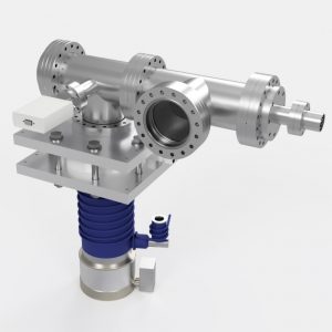
In order to run simulations in Molflow+, a proper input file must be configured and generated. Molflow+ allows user to import .STL files for simulations, in addition to creating custom geometries in the software itself through the user interface. For the following simulations, a simplified model was generated, with proper load parameters applied to the related facets. The first step of the process is to utilize the pre-existing final CAD model of the V5 System assembly. The full assembly model is as follows:
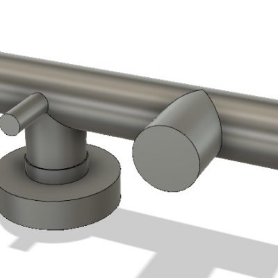
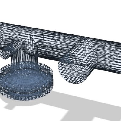
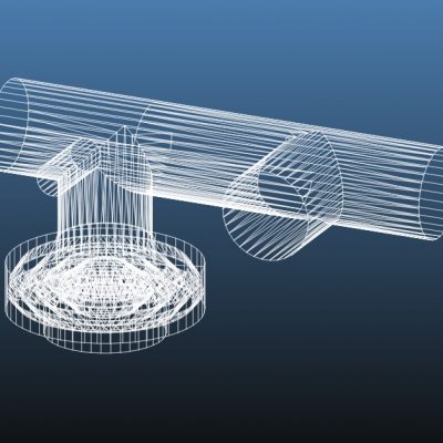
In order to create the proper .STL geometry for simulation, the model was further reduced to creating the remaining internal geometry of the system. This process follows the same steps of simplification as seen in the prior Molflow simulation with the high vacuum pumping assembly. The model is first simplified to the basic internal spacing geometry in the system. After simplification, an .STL file was generated. Because of the small size and relatively simple geometry of the pumping setup, only low mesh settings were utilized, giving more than sufficient resolution for the final simulations with reasonable run times. Finally, the binary STL file was converted to an ascii STL file, and imported into Molflow, which was collapsed and refined for Molflow simulation.
VACUUM PARAMETER FACET ASSIGNMENTS
To make simulations easier for running multiple cases of outgassing loads, the major outgassing load groups were selected and saved. Each selection represents the major load associated with the selection, assigned to the facets. Actual numbers used for outgassing for every component and material in the system were previously calculated. Outgassing load calculations can be found in the Engineering Design Calculations section of the Micro Propulsion Testing Chamber documentation page. Major gas loads included in the simulation are outgassing from wall materials during pumpdown, as well as the total outgassing load from the various o-rings in the system, which uses the combined total gas load from outgassing as well as permeation.
Three different simulations were run to compare differences in ultimate pressure based on system conditioning. For each condition, appropriate calculated loads due to outgassing an permeation were calculated and applied to the respective facets. The simulation runs are as follows:
- Simulation 1 – Unbaked, Pumped for <1 Hour
- Simulation 2 – Unbaked, Pumped for >24 Hours
- Simulation 3 – Baked, Pumped for >24 Hours
The following PDF file includes all of the facet parameter assignments for all three simulations:
SIMULATION RESULTS: MOLECULAR TRAJECTORIES
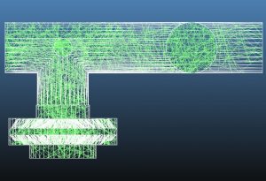
Below is a snapshot of average trajectories of pumped molecules in the system.
For the fairly large diameter 6″ conflat hardware, along with clear pumping line, and almost direct attachment of the pump to the main chamber, molecular trajectories appear to be mostly uniform throughout the chamber. As in previous simulations, a large number of particle-wall interactions can be observed between the top and bottom baffle fin sets, exemplifying the effectiveness of the baffle for preventing backstreaming.
With a pumping speed of 600 l/s with air at 273.15K, the resulting calculated effective speed at the inlet of the chamber is around 342 l/s for Simulation 1. This value drops slightly, to 264 l/s for Simulation 2, and to 258 l/s for Simulation 3.
SIMULATION RESULTS: PRESSURE MAPPING
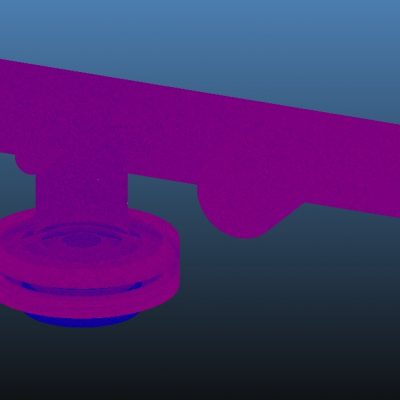
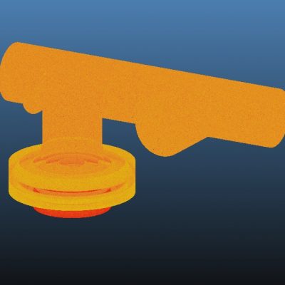
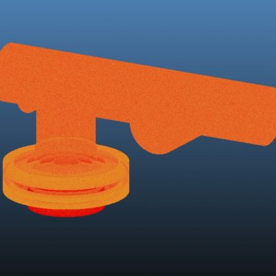
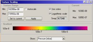
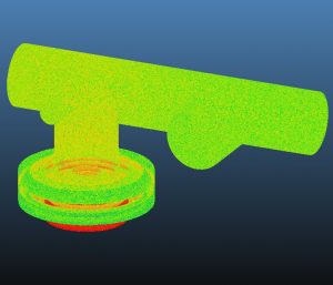
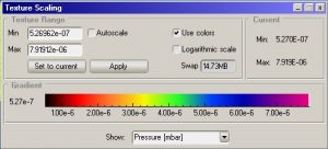
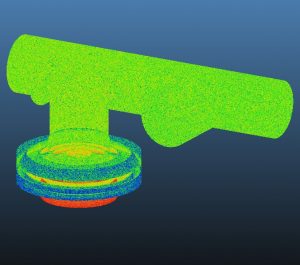
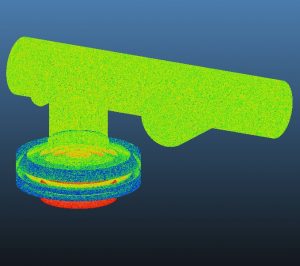
The following simulation results show the pressure mapping for each of the three simulation conditions for direct comparison of changes in ultimate pressures in the system between the cases. From left to right, the results show Simulation 1, Simulation 2, and Simulation 3 respectively. The following results depict the same simulation plots, only compared now with normalized log scale mapping for direct comparison between each of the cases:
SIMULATION 1: UNBAKED SYSTEM, PUMPED FOR <1 HOUR
Simulation 1 explores the ultimate vacuum of the full system for outgassing load parameters for all materials in the system when unbaked and pumped for less than one hour. Gas loads for each facet assignment are detailed above for reference. Each outgassing load was calculated based on surface area, material, and associated outgassing rate of the material for unbaked materials pumped for less than one hour. The pump speed of 600 l/s was applied at the baffle inlet, using air at 293.15K for simplicity. Real leaks, virtual leaks, and backstreaming from the pump were also neglected for simplicity.
From the simulation results, it can be seen that the pressure of the entire system remains very constant with little change in pressure. It can also be seen that, assuming no leaks and minimal backstreaming from the pump, the target pressure in the 10^-6 mbar range can be achieved with the system for outgassing loads of materials only pumped for about an hour. due to the very short and optimized pipeline, and direct connection to the large diameter and open chamber, pumping speeds remain high for the system, resulting in a very even pressure distribution, as well as relatively low pressure, despite the numerous o-ring gaskets used for the baffle and plate adapters. These results are very important in that the demonstrate that the system can reach desired vacuum levels in relatively short pumping times, which would allow for rapid experimenting and prototyping with opening and re-closing the chamber without detrimental effect on the overall performance if needed.
SIMULATION 2: UNBAKED SYSTEM, PUMPED FOR >24 HOURS
Simulation 2 explores the ultimate vacuum of the full system for outgassing load parameters for all materials in the system when unbaked and pumped for greater than 24 hours. This represents a much better pumped and prepared system as opposed to Simulation 1, which is to be expected during the very first pumpdown of the system. Gas loads for each facet assignment are detailed above for reference. Each outgassing load was calculated based on surface area, material, and associated outgassing rate of the material for unbaked materials pumped for greater than 24 hours. Like the previous simulation study, the pump speed of 600 l/s was applied at the baffle inlet, using air at 293.15K for simplicity. Real leaks, virtual leaks, and backstreaming from the pump were also neglected for simplicity.
From the simulation results, we can observe almost two orders of magnitude improvement in ultimate pressure of the chamber. While the pressure profile behavior is still relatively the same, with very even distribution across the entire chamber, the pressure is now well within around 6 x 10^-8 mbar. Around the baffle and the pump exhibits a bit more pressure differential from the previous simulation result due to the improvement of outgassing from the o-rings, however the overall pressure of the system is still largely uniform. These results show that with a well conditioned system in an ideal case, better than anticipated pressures can be reached.
SIMULATION 3: BAKED SYSTEM, PUMPED FOR >24 HOURS
Simulation 3 explores the best possible case scenario for ultimate vacuum of the full system for outgassing load parameters for all materials in the system when baked thoroughly and pumped for periods of greater than 24 hours. This represents ideal UHV system preparation with fully minimized outgassing from all materials present in the system. Like the previous simulation studies, the pump speed of 600 l/s was applied at the baffle inlet, using air at 293.15K for simplicity. Real leaks, virtual leaks, and backstreaming from the pump were also neglected for simplicity.
As can be seen from the above simulation results, the ultimate pressure of the system does not improve significantly from the previous case. With the applied outgassing loads, the resulting ultimate pressure at the inlet of the chamber barely drops further, to about 5 x 10^-8 mbar. This shows that even with baking and pumping for extended periods, better vacuum performance cannot be expected with the current setup. This is primarily due to the ultimate vacuum limitations of the systems set by the permeation of air through the viton o-rings. Baking will however allow the system to reach it’s best ultimate pressure at a must faster rate than without baking, but ultimate pressure will not be affected.
SIMULATION RESULTS: PRESSURE PROFILE PLOTS
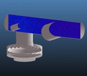
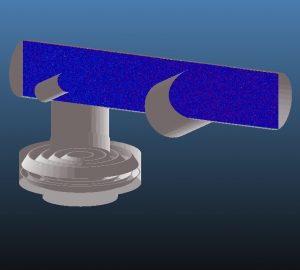
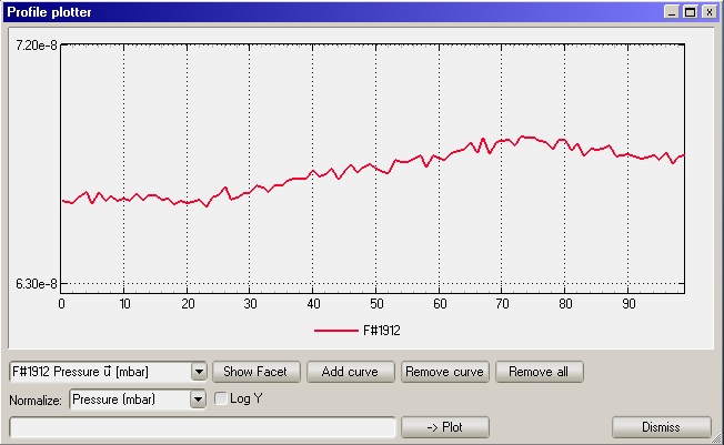
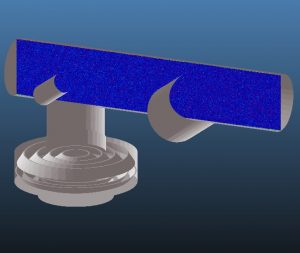
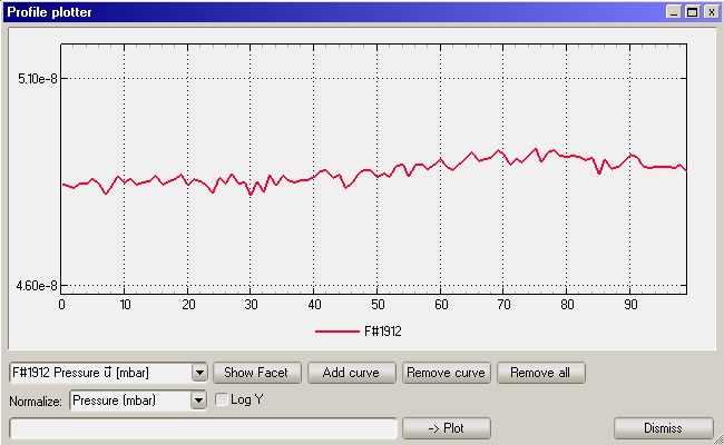
For the following results, a transparent measurement plane was added to intersect the main chamber vertically through the center, as well has horizontally through the 4-entire length. The resulting pressure plots show the changes in pressure through the system from the inlet of the diffusion pump to the blanked-off chamber inlet. This also allows for better calibration of vacuum gauges in predicting the difference in resulting pressure between the measurement plane and the actual chamber due to differences in conductances and pumping speeds in the system. Both linear and log views are shown for comparison. Y-axis units are in mbar, x-axis units are arbitrary length units, for which the measurement plane is divided into 100 equal segments.
SIMULATION 1: UNBAKED SYSTEM, PUMPED FOR <1 HOUR
I. Measurement Plane
II. Pressure Profile Plot Results – Chamber Pressure Profile Linear Scale
SIMULATION 2: UNBAKED SYSTEM, PUMPED FOR >24 HOURS
I. Measurement Plane
II. Pressure Profile Plot Results – Chamber Pressure Profile Linear Scale
SIMULATION 3: BAKED SYSTEM, PUMPED FOR >24 HOURS
I. Measurement Plane
II. Pressure Profile Plot Results – Chamber Pressure Profile Linear Scale
DISCUSSION
The above plots show the pressure profile of the main chamber, from left to right, divided into 100 equal segments. From the results, we can see that in all three simulation cases, the pressure of the main chamber remains very constant along the entire length. A slight dip is seen around point 20 on the x-axis, representing the point in along the chamber that is directly above the pumping port. Likewise, the peak pressure in the chamber occurs between points 70 and 80, which is the area directly in front of the viewport, which exhibits higher outgassing load from the glass than the stainless steel.
In terms of final pressure of the chamber, as discussed in prior sections above, there is a significant difference in the pressure between Simulation 1, and Simulations 2 and 3.This difference is almost two orders of magnitude for a new system with minimal conditioning, and a well conditioned chamber. However, as noted, due to the high pumping speed of the system, the target ultimate pressure in the 10^-6 mbar region is achieved still even with an unconditioned chamber. Between extended pumping and baking with extended pumping however, there is diminishing returns for ultimate pressure. Between Simulations 2 and 3, there is minimal difference. While slight improvement is achieved through baking, the ultimate pressure is limited due to the permeation of gas through the viton o-rings used with the baffle and adapter plates. However, as also noted, baking will drastically decrease the time required to achieve this level of vacuum. In addition, the pressure profile of the chamber becomes even more even and uniform from the first to the last simulation. The larger bump in Simulation 1 due to the outgassing load of the viewport is drastically reduced by Simulation 3, showing overall significant improvement as outgassing loads diminish with improved conditioning.
CONCLUSION
An in-depth and detailed study of molecular flow simulations using Molflow+ for the Micro Propulsion Testing Chamber and pumping assembly is presented. Simulation results show that with improved system preparation, increasingly higher vacuum levels can be expected, however the ultimate pressure is limited due to gas loads from the viton o-rings. However, due to the high pumping speed of the system, and optimized pumping pipeline, desired vacuum levels can be achieved with relatively little conditioning of the system. The simulations verify that the pumping assembly can easily reach the desired ultimate pressures in the 10^-6 mbar regime, and even can achieve levels in the UHV region.
SIMULATION FILES
-
Micro Propulsion Testing Chamber Final – Unbaked and Pumped 1hr.ZIP
-
Micro Propulsion Testing Chamber Final – Unbaked and Pumped 24hr.ZIP
-
Micro Propulsion Testing Chamber Final – Baked and Pumped 24hr.ZIP
-
Micro Propulsion Testing Chamber Final – Unbaked and Pumped 1hr Pressure Profile Facet.ZIP
-
Micro Propulsion Testing Chamber Final – Unbaked and Pumped 24hr Pressure Profile Facet.ZIP
-
Micro Propulsion Testing Chamber Final – Baked and Pumped 24hr Pressure Profile Facet.ZIP
RELATED STUDIES

