I. TESTING SUMMARY
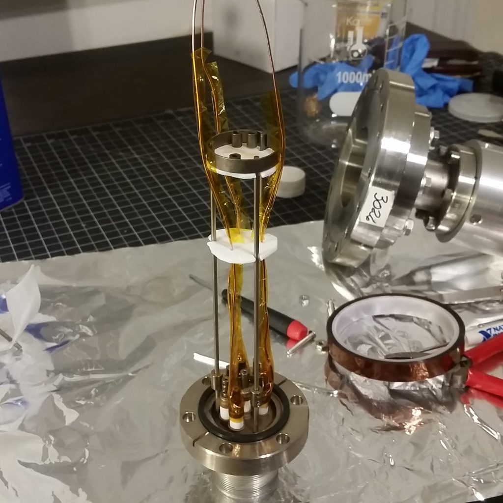
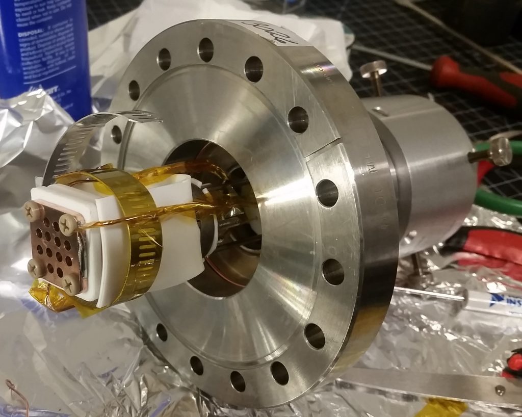
Immediately after the prior day’s unsuccessful ignition attempt of the AIS-uPPT1 Micro Pulsed Plasma Thruster, preparations were made to mount the second thruster in the chamber and begin ignition testing of the AIS-gPPT1 Gridded Pulsed Plasma Thruster. Over the two days after the first thruster test, I cleaned, mounted, and wired the thruster to the conflat vacuum feedthrough, checking all connections, adding insulation, and mounting the test assembly to the propulsion chamber.
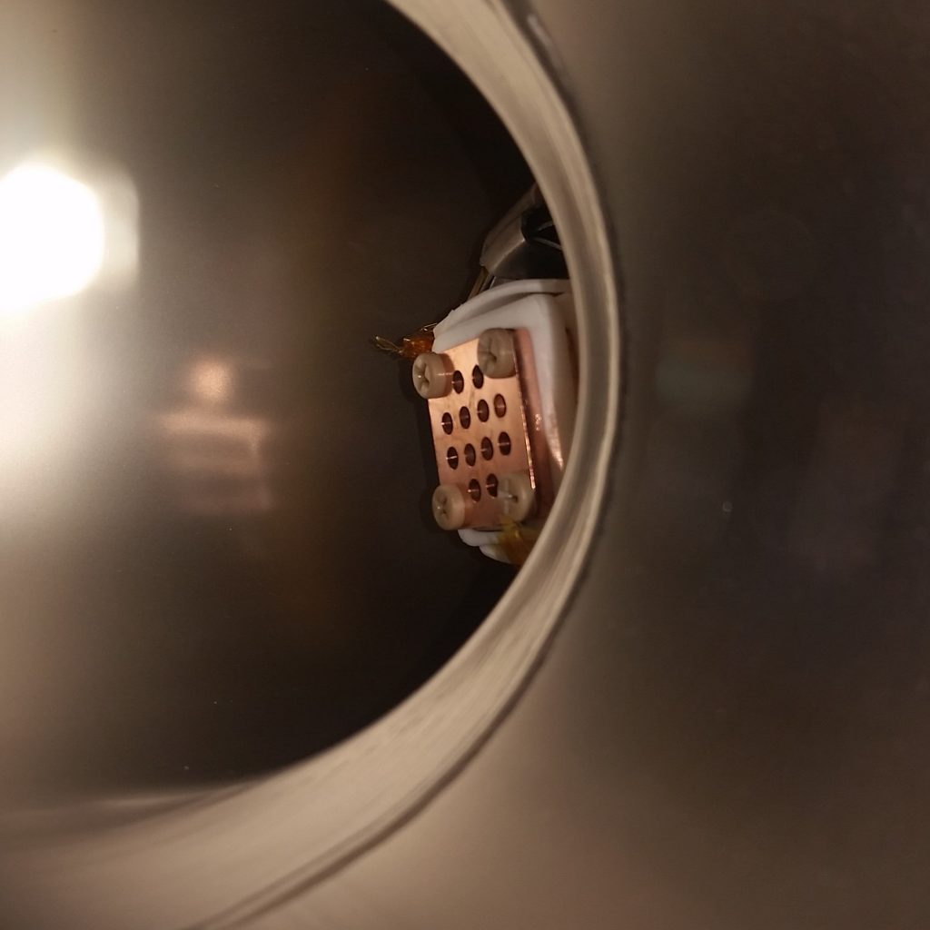
With the preparations set, and all high voltage supplies ready to go, I began the first ignition test of this thruster, on May 7th, 2019. Like the prior vacuum tests, I live tweeted every detail of the test on the Applied Ion Systems Twitter page. The chamber was pumped down from atmosphere to a vacuum level of 1×10^-5 Torr before ignition testing began. Like the previous test, both ignition voltage and main capacitor bank voltage was slowly raised. The trigger pulse was firing, but no ignition was observed. The voltage was increased higher until arcing was observed in the connections behind the thruster. In an attempt to achieve ignition, I continued to push the system despite the arcing faults. Soon after, arcing was actually observed between the 8020 test stand table and nearby thermocouple shielding wire running from the cooling system. Something was severely wrong, and appeared to be a major grounding issue. I had initially planned the chamber to be floating to prevent arcing from the supplies to the chamber walls due to the tight internal spacing for the connection wires. I thought the chamber was isolated, but apparently the high voltage was still making its way through the chamber and even into the metal test stand. As the voltage of the igniter was increased, it began arcing to the conflat connection, meaning the chamber was in fact still grounded. The only connection this could occur through was the HPT-100 gauge cable. I unplugged the gauge, and external arcing ceased. At this point, due to the arcing internally, as well as externally, the Arduino Mega had crashed, and I could not establish any communication with the cooling system or vacuum system sensors. I was running blind with no cooling or vacuum data. Manual checks of the diffusion pump and cooling tanks with my hand confirmed that the system was not running too hot, and since everything was operating at nominal conditions before the crash, it was highly likely that vacuum was stable in the upper 10^-6 range since my last vacuum pressure check.
During the testing and chaos of failing electronics, after unplugging the vacuum gauges and disconnecting the chamber from ground, I managed to witness four, countable, random ignitions of the thruster. The thruster did fire properly a handful of times, however ignition was highly inconsistent, and only occurred a few times out of hundreds of ignition pulses.
II. FAILURE ANALYSIS SUMMARY
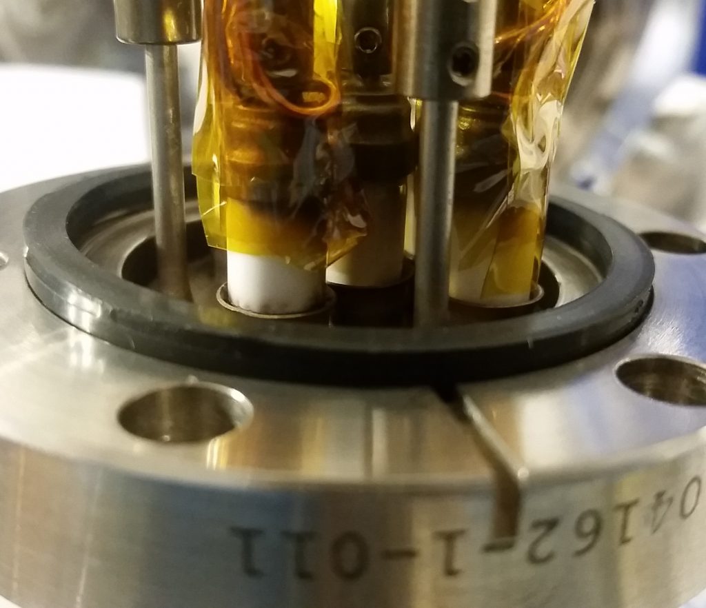
Upon de-mounting of the thruster assembly on the conflat feedthrough from the chamber, several areas of failure were immediately observed. The arcing that was observed during testing was found to occur at points where the Kapton tape insulating the bare conductors ended. The prior ignition test had the same setup and parameters – the only difference between these two tests were the thruster being tested, and the addition of Kapton tape as insulation for this test. The prior test did not include any Kapton tape insulation. It is suspected that outgassing and volatiles from the relatively cheap generic brand Kapton tape adhesive that was purchased from eBay, coupled with the high voltage pulses, initiated arc discharges at areas where the conductors were close and were the adhesive was exposed.

III. EQUIPMENT DAMAGE SUMMARY
After inspection of the thruster assembly, I started testing and debugging of the electronics, due to the loss of communication with everything during the test. Over the next couple of days, I confirmed my worst fears. The damage was significant and massive. The Arduino Mega, RS-485 converter, HPT-100 vacuum gauge, 24V DC gauge power supply, DHT22 ambient temperature/humidity sensor, and 3 out of 6 thermocouple channels (channels 4, 5, and 6) were destroyed. While most of the parts were relatively small and cheap to replace, the most devastating loss was the HPT-100 gauge. The gauge was purchased for incredibly cheap on eBay, for only $40, where a new equivalent gauge would normally cost thousands. The gauge was also very lightly used, in almost new condition. No testing can occur without a vacuum gauge to know what vacuum level I am operating at. This particular gauge is also a very powerful piece of equipment, allowing me to see the entire range from atmosphere all the way down to 10^-10 Torr seamlessly, and is a crucial piece of equipment for allowing me to not only monitor vacuum during testing, but record crucial pumpdown data for each test.
The next day, I started the repairs. I also decided to test the other 3 spare gauges I had purchased on eBay. Unfortunately, the bad news just kept pouring in. All three spare gauges appeared to be non-functional as well. Over the course of the next couple of weeks, I began to obtain replacement parts. i managed to located two lightly used and verified functional HPT-100 gauges on eBay which I purchased, though at a relatively high price. The gauges were also KF40 instead of 2.75″ CF, meaning I needed to get an additional adapter to mount these new gauges to the chamber port. The total repairs ended up being a significant cost that I am still recovering from, and has set me back from further testing for several weeks.
IV. FULL TESTING AND FAILURE ANALYSIS REPORT
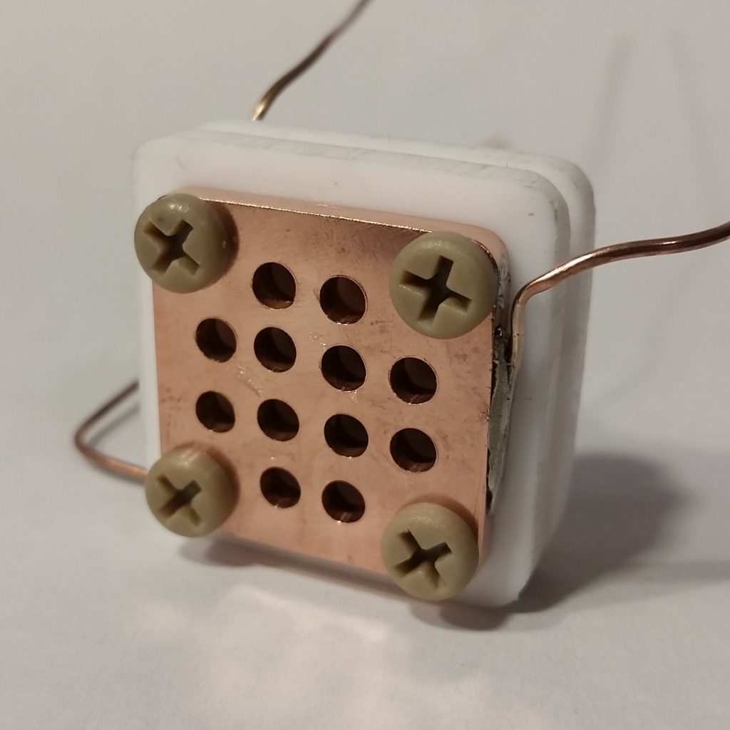
Below you can find the full and complete final testing and analysis report for the first ignition test of the AIS-gPPT1 thruster. Like the first testing report from the previous test, outlined in my last blog post, this report includes full test parameters, test procedure, failure analysis with pictures, and recommendations for future testing and thruster improvements. The instrumentation damage from this test was significant. However, like the previous test, the main underlying issue was that the thruster design did not operate correctly at the proper voltage, and as a result, caused damage as the voltage was pushed higher and higher to achieve ignition. The main cause of ignition failure in the design has been attributed to the igniter-cathode spacing, as well as the use of flat, wider-surface area igniter pins instead of the conventional sharper ignition pins seen in standard PPTs. Although lifetime and erosion should improve with larger surface area pins, the set spacing of 0.0625″ was too far to initiate proper discharge. Going forward, the ignition pin spacing will be greatly reduced and reconfigured for the next generation of gridded pulsed plasma thrusters in development.