On August 9th, 2019, I officially revealed the final design for V1 of the new AIS-gPPT3-1C Series Integrated Propulsion Module on social media. The final PCB design had been in the works several weeks prior, and the design was finally ready for manufacture. Below are the KiCad renders of the new board design:
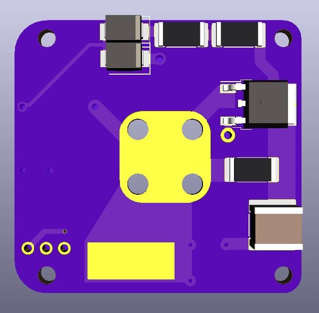
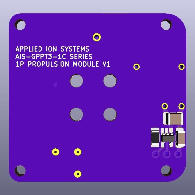
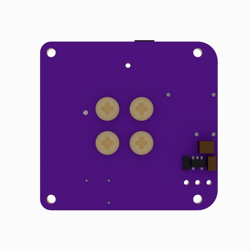
As mentioned prior, this module is specifically designed for compatibility for 1P PocketQubes. Final board footprint is only 38mm x 40mm, with the option to easily adjust hole spacing as needed for standard or custom PocketQube mounting. Less than 1W power consumption, with the ability to power and control the module directly from 3.3V power and signals from standard PocketQube electronics. Not shown in the KiCad render is the thruster assembly (mounted to the large center pad), the EMCO Q-Series supply (mounted to the left of the center copper region), the main capacitor bank (lower exposed copper pad), and ignition transformer for the igniter (just right of the bottom exposed pad.) As you can see, the board is incredibly simple, consisting of a basic charging supply which charges the main bank and igniter cap simultaneously, and a thyristor for triggering the pulse transformer for ignition. On the back of the board is a small load-switch circuit allowing for direct enabling and disabling of the EMCO power supply.
In addition to the board layout, I also finalized CAD models for the fully assembled propulsion module, showing the exact placement of all the components, holes, and thruster on the board as a completely integrated package, and how it will be in real-life. These models will be available on the propulsion module main page for download so that other PQ developers can integrate the system in their designs. Below are some CAD model renders of the fully assembled thruster:
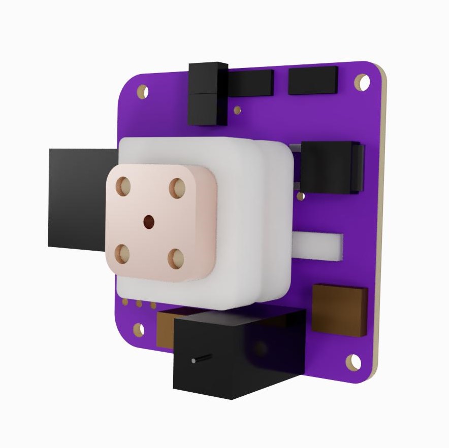
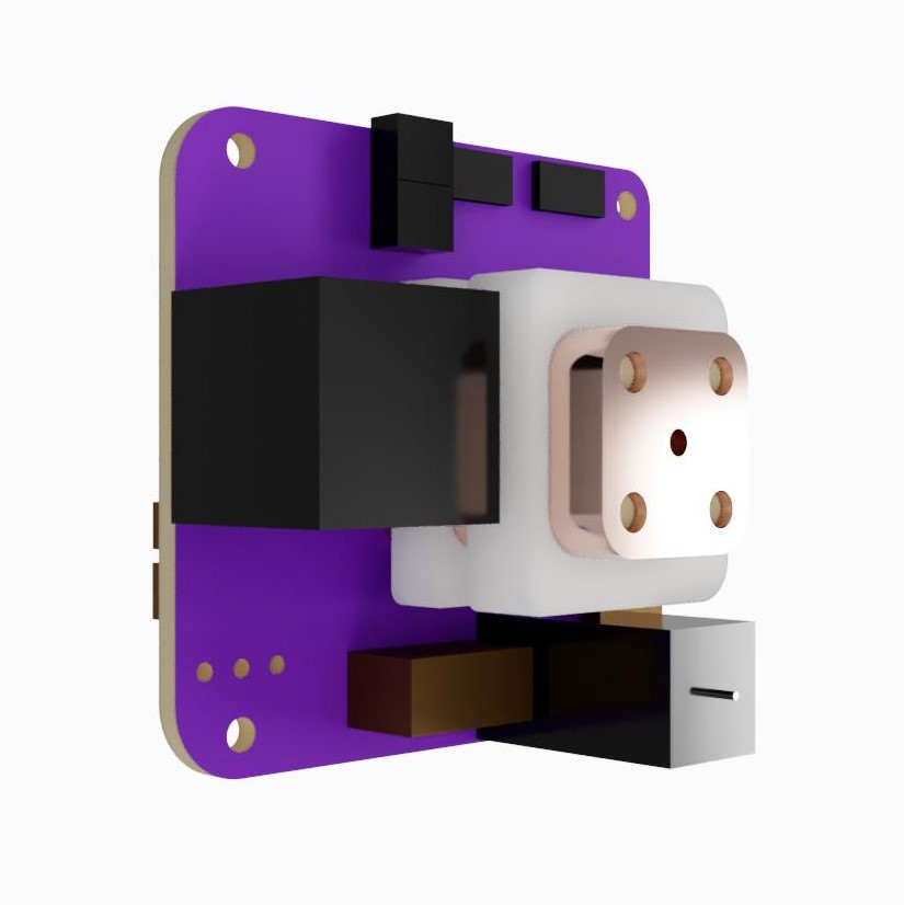
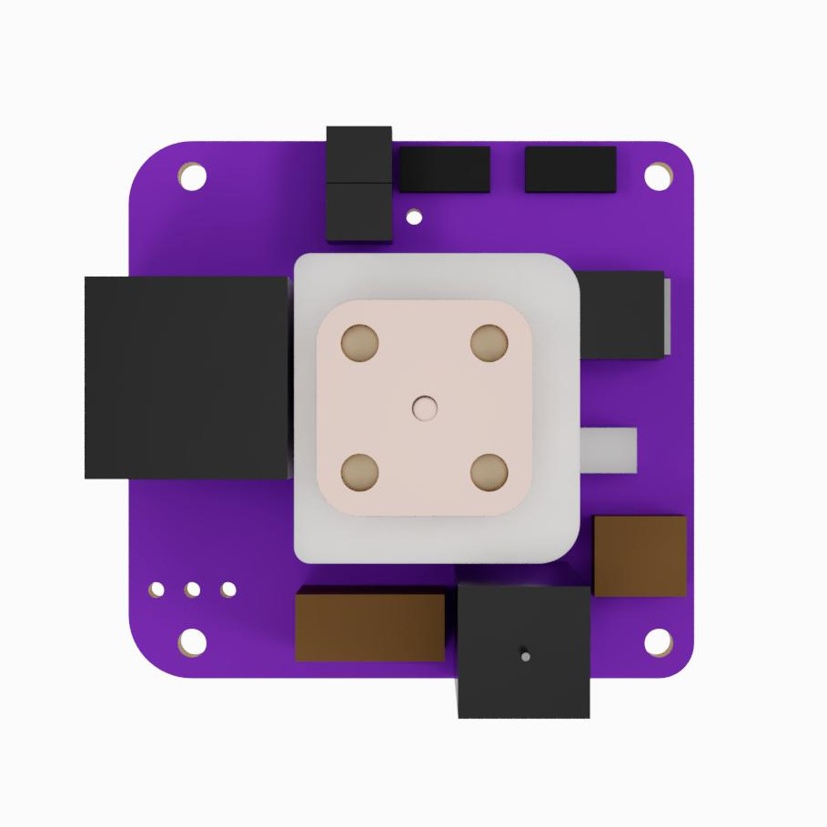
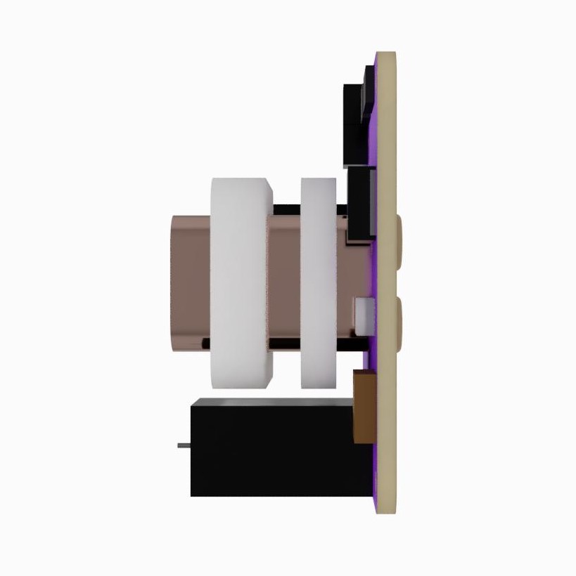
A major technical challenge of this design was fitting the 2kV supply and 12kV ignition circuit in such a tight space. I tried to maximize spacing between HV and ground as much as possible while trying to keep path inductance low and close for the major pulse connections. As a result, there are a few things to note for final assembly. The main bank SMT caps are soldered vertically rather than horizontal on the board. Point soldered connections with UHV-rated high voltage Kapton insulated wire will be made from the main bank output to caps, caps to anode, and pulse transformer to igniter.
Stay tuned for following posts where I go over the actual fabricated boards and initial atmospheric testing in preparation for the big upcoming vacuum tests to fully qualify the boards! Once they pass vacuum testing, the propulsion modules will be made available, making this the first ever PQ-specific completely integrated propulsion solution on the market!