Progress has been moving along quite rapidly with development of the AIS-gPPT3-1C series micro pulsed plasma thrusters. Having talked with numerous PocketQube developers in the PocketQube community, I have been narrowing down the final specs for the electronics module for the thruster assembly. Essentially, the thruster must be full compatible with a standard PQ in terms of size and power restrictions. Currently, there are two versions of the thruster being developed – a low power module for 1P PocketQubes, and a higher power module for 2P/3P PocketQubes. One of the biggest challenges is getting the power supply down to a low enough power draw to be viable for these incredibly small satellites. As of now, no propulsion solution exists on the market specifically for PocketQubes, and scaling down, even for the much larger class of Cubesats, has remained a formidable challenge in the field.
The goal for development is starting as small as possible, and scaling up. Current propulsion efforts have always focused on starting with larger-class units, and scaling down. In the propulsion field, one of the biggest challenges is in fact scaling down, both in size and power requirements while still keeping acceptable performance. Instead, since I am working on a radical class of ultra-low energy PPTs, I have decided to start as small as possible, and scale up, since this route is much easier.
The design of the thruster is at this point set for the V1 version of the module. The first prototype delivered will be the 1P class module. Discussing requirements and compatibility with the PocketQube community, there was one major design element for the power supply that needed to be addressed.
Based on power restrictions, it was decided to go with the EMCO 0.5W Q-series high voltage supply for the 1P module, and the 1W AG series for the 2P/3P module. Note that the wattage ratings for these supplies are the power output, not input. The supplies are only about 66% efficient, meaning larger losses than I would like. However, the supplies are incredibly small, and with isolated outputs, which is very beneficial for the pulsed thruster, it is very difficult to improve efficiency at this stage for size scaling. The Q-series supplies for example, up to 2kV out, are only 0.5″ cubes in size! Impressively compact! In addition, EMCO supplies have been widely selected and utilized for space applications and propulsion, and have been demonstrated as flight-heritage technology. The Q-series has in fact been flown before on the STRaND-1 Cubesat in 2013 (which I will address again below.)
Now, these supplies are normally rated for 5V input. However, this presented the first concern for PQ integration. Standard PQ supply voltages are on the order of 3.3-3.7V DC. In order to get the 5V required, a 3.3-5V boost converter would be necessary. There are surface mount boost converters that are over 90% efficient for the voltage and current levels I am aiming for. However, that introduces more power loss, and adds additional circuitry. The Q-series supplies though can be under-driven, and have a linear output from about 0.7V to 5V, which means they can be driven directly from the 3.3V of the PQ, at reduced output.
The original plan was to use the Q15-5 module, which outputs 1.5kV. However, under-driving this at 3.3V would produce much less voltage. The goal is to charge the main capacitor bank to at least 1kV during nominal operation in a reasonable time, at rep rates of around 1/3Hz. What if we were to drive a higher voltage module at lower input voltage though? As voltage increases, the available current decreases. How would these two scenarios compare, and how would it affect ultimate performance? Would it be better to use the 5V boost converter, or directly drive the module with 3.3V?
Based on these questions, a study was performed to compare charging performance and power requirements for two different cases. Case 1 looks at 5V input to the 1.5kV Q15-5 supply. Case 2 looks at 3.3V input to the 2kV Q20-5 supply.
Below, you can see the resulting graph from the comparison study. The circuits were simulated for each case, charging the main bank as well as the igniter capacitor, with bank capacity sized for equivalent voltages of 1kV at 3 seconds charging time.
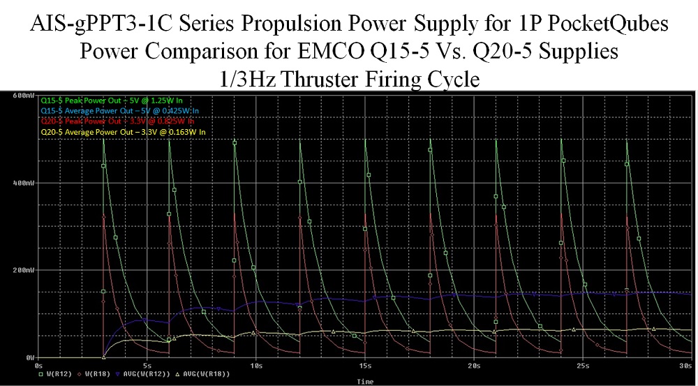
The graph shows both the peak output power as well as average output power for both cases. In Case 1, for 5V in, 1500V at 0.33mA out, a 0.4uF bank would take 3 seconds to get to 1kV, with an energy of 0.24J. In Case 2, for 3.3V in, 1320V at 0.2mA out, a 0.2uF bank would take 3 seconds to get to 1kV, with an energy of 0.12J.
For Case 1, peak output power is 500mW, corresponding to a peak input of 1.25W max at 3 seconds charge, but drops rapidly to 35% load in 1s. For Case 2, peak output power is 330mW from the max of 500mW, corresponding to 825mW max on the input, dropping to ~14% load at 1s.
For the Case 1 peak power of 1.25W in, 500mW out, the average power over the firing cycle corresponds to 425mW in, 170mW out. For Case 2, which is under-driven, for 825mW in, 330mW out peak, the average power requirement over the firing cycle is 163mW in, 65mW out.
Here we can see that directly driving the Case 2 supply at 3.3V in under-driven conditions gives us much lower peak and average power requirements for the propulsion module for the nominal firing rate of 1/3 Hz. The ultimate goal for the 1P propulsion system is to keep power draw below 1W. In this scenario, this goal is accomplished. How does this affect thruster performance though?
Here is the tricky part. Low-power electrothermal based coaxial PPTs do not follow a linear scaling trend like larger electromagnetic type PPTs. Performance scaling needs to be determined based on empirical test data for a given thruster. For the previous tested AIS-gPPT2-1C thruster, a rough correlation of I-bit=0.6744e^(1.2923*energy) was seen. Based on this, for Case 1, average I-bit may be around 0.92uN-s. For Case 2, this drops to an average of 0.79uN-s. Not huge loss, but these are only very rough estimates. In terms of thrust, for 1/3Hz we can expect rough thrust of 0.31uN for Case 1, and 0.26uN for Case 2. At this extreme low-end of PPT bank energy, it is possible that larger changes in energy may not correspond to as large changes in I-bit or thrust for a given configuration. So far the Gen 2 thruster has fired down to as low as 680V, 0.23J, making 1kV nominal bank voltages well within firing range. However, it has never been tested down to 0.12J before, and I don’t think I have ever seen a PPT designed for such low energy – truly unknown territory!
Based on the analysis, for the extremely limited power requirements of a 1P PocketQube, using the direct 3.3V under-driven Q20-5 supply may be the best route, with it’s peak power draw of only 825mW (for less than 1 second), for an average draw of 163mW, and optimizing thruster design for low energy operation. Going forward, the newest Gen 3 thruster will aim to optimize performance at this extremely low-energy level by leveraging the embedded magnetic nozzle and much tighter fuel bore. However, there are still a lot of unknowns entering this new extra-low energy realm.
In the above introduction, I mentioned the STRaND-1 Cubesat. Digging through the project analysis paper I found, there is some interesting information for comparison. The first was that the Cubesat flew with x8 EMCO Q-series modules to power their 8 onboard sub-joule PPTs. This greatly increases confidence in the curent module that I am working on, seeing that the Q-series supply is in fact space heritage and tested hardware. These PPTs however were typical electromagnetic type diverging rail thrusters, rather than the electrothermal type coaxial that I am working on.
Below is a table from the paper (reference link available at the end of this article for credit) on the expected performance specs of the propulsion system for the Cubesat:
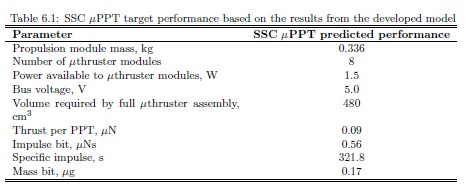
Here, we can see a few interesting things for comparison. The first, and most crucial detail here is impulse-bit, which is estimated at 0.56uN-s. Thrust per PPT is also expected to be around 0.09uN. Since we know I-bit and thrust, we can calculate repetition rate. For pulsed thrusters, thrust is simply I-bit x frequency (Hz). From this data, we can see that the STRaND-1 thrusters are expected to fire at a rate of about 0.16 Hz, or about once every 6 seconds. How does this compare with current PPT developments at Applied Ion Systems?
Here, you can find a link to the most recent test document on the previous generation thruster: the AIS-gPPT2-1C:
Based on collected data and scaling law predictions based on the results, which were discussed above in the circuit analysis for the selected Case 2, if the gPPT2-1C thruster was used with the AIS-gPPT3-1C electronics, the average I-bit can be expected to be around of 0.79uN-s. At a nominal firing rate of 0.33 Hz (twice the repetition rate of the STRaND-1), we can expect rough average thrust of 0.26uN. Note that in this case, the energy corresponds to the expected 0.12J, assuming the scaling law established for the thruster is reasonably accurate, and the thruster fires effectively at this low-energy range. This thruster actually appears to perform significantly better than the STRaND-1 thruster! Note that I am competing with state-of-the-art high funded aerospace labs, with a thruster built on my dining room table and fired in a completely self-built system, on a paltry budget! Not bad for a home-based electric propulsion space program!
Another major point to consider – the STRaND-1 thrusters were developed for a 3U Cubesat. With specs on par or better, an equivalent thruster output would go significantly farther on a PocktQube. Considering that a 1P unit is 1/4th the total volume of a 1U Cubesat, and often propulsion is made for larger 2U and 3U Cubesats, we can see that this has very exciting implications for a PocketQube thruster.
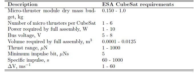
From the cited paper, we can see a few more tables referring to propulsion for CubeSats, Since PocketQubes are still unknown territory at this point, no studies have been released looking at propulsion requirements for PocketQubes. However, by looking at Cubesat requirements, we can start to see how PocketQube specs may scale. The first table shows general specifications from the European Space Agency (ESA) for Cubesat propulsion requirements:
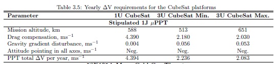
This second table shows a comparison of PPT performance specs for delta-V requirements for several CubeSat sizes. In this case, a simple, low-power 1J pulsed plasma thruster is assumed.
We can see here that PocketQube propulsion compared to Cubesat systems, for scaling may in fact be feasible. Especially since, as demonstrated with the comparison between my current thruster and the STRaND-1 thruster, PocketQube thruster specs can be on-par or even exceed current Cubesat specs (at least for PPTs). One key area that still needs to be addressed however for PocketQube propulsion, especially with PPTs, is lifetime. The current gPPT2-1C thruster does not have nearly enough lifetime. This will hopefully be solved with the new gPPT3-1C thruster. One key necessity though that is still required by the PocketQube community is a simulation study determining exactly how much thrust and I-bit is required for orbit keeping of a PocketQube, in order to extend its lifetime. Current expected lifetimes of a typical PQ in LEO is around 6 months. Numerous studies on the Cubesat front have suggested that even minimal propulsion can extend orbital lifetimes by a factor of 2-3. If it would be possible to double the lifetime of a PocketQube, value of the small satellite immediately increases. With the current plan to keep propulsion modules as low-cost as possible (around the $1k to several $k range), this can significantly enhance PocketQube capabilities and value, and opens up a wide range of new options, such as longer orbit times, orbital transfers, de-orbiting, and other in-orbit maneuvers currently only available for larger and higher cost satellites.