In my previous post on the fueling phase for the second test of the of the AIS-ILIS1 ionic liquid electrospray thruster, I went over the fueling and degassing cycle in preparation of ignition. In this post, I will review the actual ignition test attempt. Below is a picture of the fully fueled and assembled ILIS1 with the V5 board.
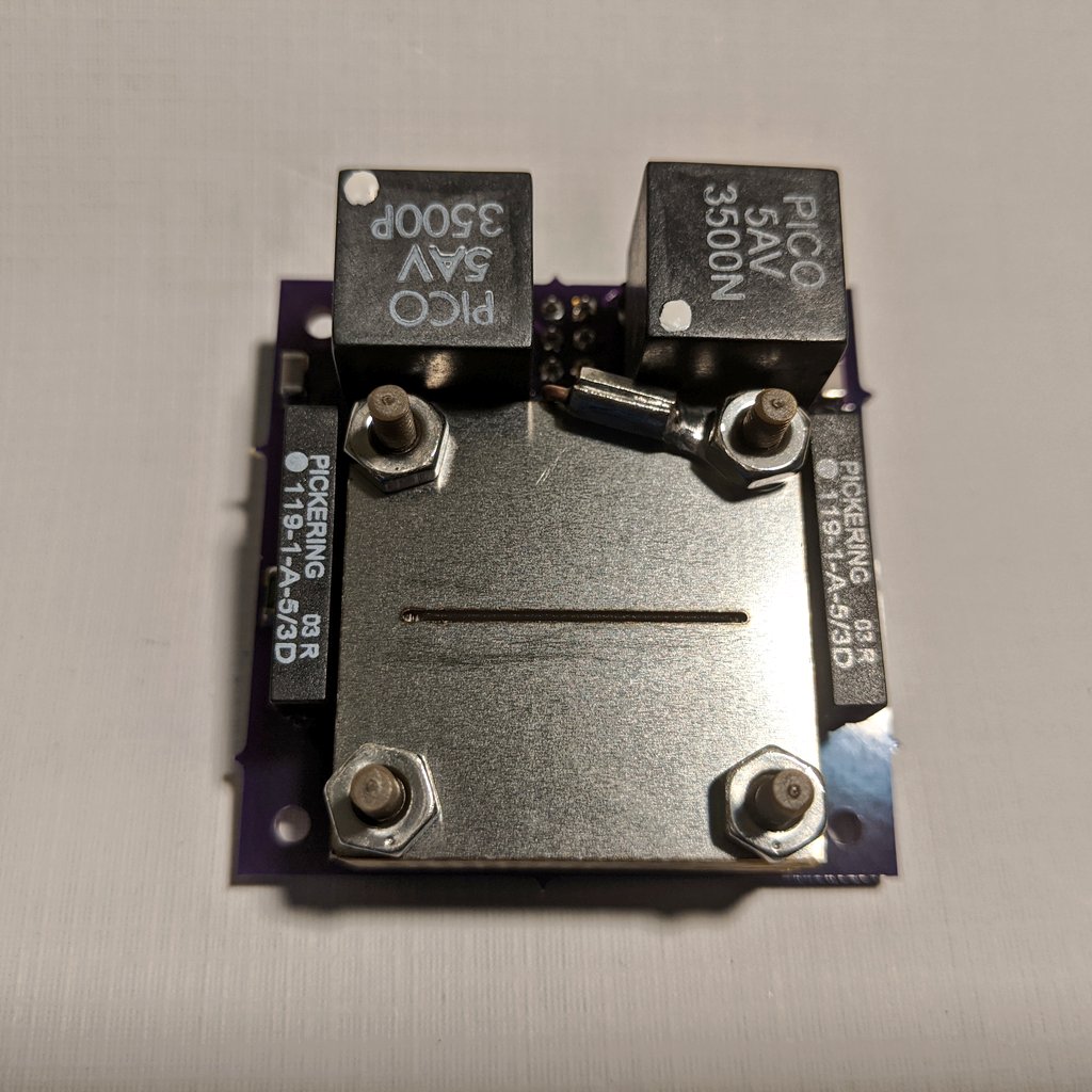
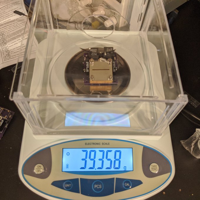
The wet mass for this test was checked with a better scale I purchased recently off Amazon for a great price, at 39.358 grams. This slightly lower mass from the prior found 40 grams during the first ignition test is most likely due to the modified Ultem printed housing, vs. the unmodified Accura 48HTR resin print used prior.
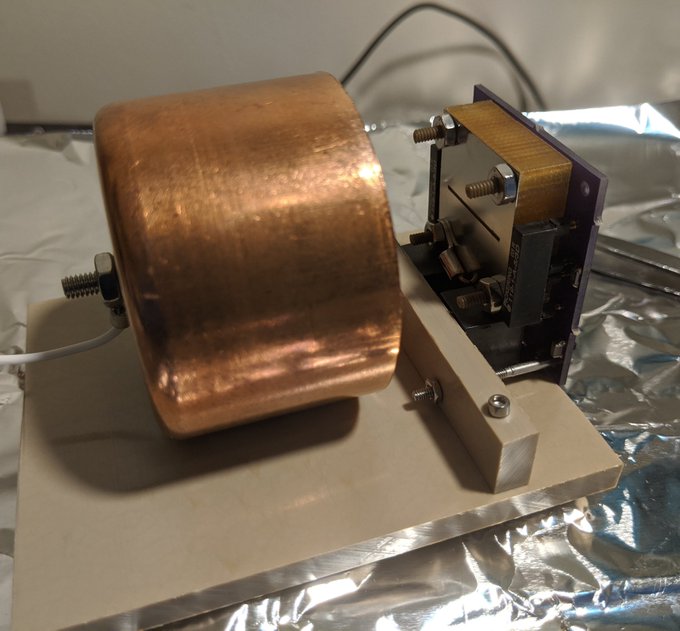
Here we seen the thruster mounted to the Faraday cup test stand prior to loading it into the high vacuum chamber and wiring it up for testing.
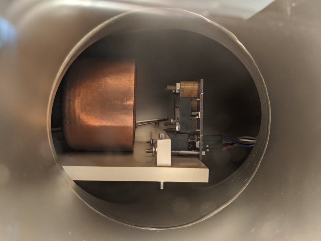
With the test stand positioned and aligned in full center of the viewport, and the instrumentation and control ports wired up on either end, it was time to begin the pumpdown cycle for ignition.
For this test, there were a few key differences from my first attempt. The biggest is that the emitter to extractor distance had been adjusted to be exactly in line as it should have been, 0.5mm closer for 0mm clearance edge to edge, as it was previously found that the prints were 0.5mm too thick at the top, creating too large of a gap between the emitter and extractor. I also switched out the 1mm wide aperture extractor for the 0.75mm wide extractor to help increase the field strength at the emitter and allow for lower turn-on voltage. I also adjusted the thruster timing in the control software to slow down cycling by a lot. Each polarity would be on for 5 seconds, then have a several hundred ms pause and transition. Too fast cycling under light loading last time most likely caused over-voltage in the relays. The longer transitions would help mitigate this issue, and allow for plenty of time for the remaining charge in the HV filter caps to bleed off. Longer time on for each polarity would also allow the thruster to condition and settle a bit more stably during operation. Finally, both the fuel and casing were baked and degassed, and the full thruster assembly would undergo a second light bakeout at 60C max during pumpdown before firing. This second pumpdown would help reduce the chances of faults from outgassing products with the high voltage. All HV points were filed smooth on the board as a further precaution.
Pumping and light baking went well without issue for several hours. Once a final pressure of 3×10^-5 Torr was achieved, preparations were made to begin the ignition sequence. The control sequence was first started without external power applied for the HV power input. External power from the adjustable power supply was then slowly brought up. The Pico HV supplies on board the thruster turn on at about 2.5V.
While not perfect, I soon saw the characteristic faint glow of ion emission emanating from the far corner of the extractor slit, at around 2200V, exactly as predicted. Unfortunately, for unknown reasons, the -HV supply suddenly failed, leaving me only with the +HV side cylce. However, this was mode than enough to proceed with the test.
Power was slowly increased to the thruster. Only one glitch in the Arduino occurred, requiring a quick restart, but no further issues were encountered after. The glow increased intensity until catastrophically shorting after further power increase.
While not a full success, this test was a massive step forward in the right direction, and a major improvement from the first ignition attempt. Unfortunately the thruster eventually shorted as power was increased, however I was able to captured over a minute of video of the system operating with stable, controlled, partial emission during the +HV cycle in operation. In the next post, I will review the captured video footage of actual ion beam emission!