UPDATE LOG
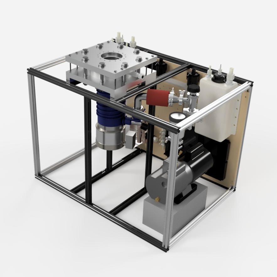
- 10/21/2018 – CAD model of finalized Integrated High Vacuum Test Stand layout completed, with the 8020 test stand, cooling system, foreline pumping system, and high vacuum pumping assembly merged into a single file.
- 10/21/2018 – Official engineering specifications project documentation page released.
- 10/27/2018 – Diffusion pump to water cooled baffle plate modified for standard o-ring size. Water cooled baffle to chamber adapter plate modified to remove 6″ conflat knife edge from custom mating joint and replaced with 0.015″ deep flat groove for direct compression mating to reduce manufacture costs and complexity.
- 10/28/2018 – CAD assemblies updated to reflect adapter plate modifications. Initial high vacuum calculations for estimating system effective speed at chamber adapter inlet as well as ultimate blanked off pressure complete.
- 10/30/2018 – Pumping speed vs atomic mass unit estimates completed and graphed for pump speed vs chamber inlet effective speed for both molecular and transitional flows.
- 11/08/2018 – Initial molecular flow calculations on the integrated high vacuum diffusion pump system is completed and verifies viability of 600 L/s pump for reaching desired ultimate pressure of 10^-7 torr blanked off.
- 11/15/2018 – Molecular flow simulations and analysis using Molflow+ for the diffusion pump assembly is complete. Full simulation report page added to the Simulations page.
- 01/09/2019 – Aluminum adapter plates manufactured
- 01/20/2019 – Aluminum adapter plates modified with Loctite steel studs for mounting to reduce stresses on aluminum threads in plates
- 01/22/2019 – Foreline redesigned and reconfigured using large diameter natural gum hose for direct adapting to diffusion pump inlet.
- 01/25/2019 – Foreline preliminary assembly and first roughing test complete. Foreline pump blanked-off achieved 13 milliTorr, while the full system achieved 23 milliTorr.
- 02/02/2019 – 80/20 reinforcements added to the table – structural elements finalized and complete.
- 02/07/2019 – Diffusion pump disassembled, cleaned, and filled with new 705 oil. Full high vacuum pumping stack sub-assembly bolted together and completed.
- 02/13/2019 – New cooling fans added to cooling system.
- 02/21/2019 – Cooling system wiring completed, routed, and tested.
- 02/22/2019 – High vacuum pumping stack mounted to Integrated Test Stand and final cooling lines run.
- 02/27/2019 – Slight leak in TC3 repaired. Final cooling system leak test check run.
- 03/03/2019 – CAD model updated for final revision including new foreline configuration.
- 03/30/2019 – Test stand moved to final testing location
- 04/05/2019 – Cooling system power lines wired
- 04/25/2019 – Micro Propulsion Testing Chamber mounted to Integrated Test Stand
- 04/26/2019 – Roughing assembly mounted to test stand
- 04/27/2019 – Final power cables wired and mounted to Integrated Test Stand. Test stand is now complete and ready for high vacuum testing.
- 05/01/2019 – FIRST MAJOR APPLIED ION SYSTEMS MILESTONE COMPLETE! SUCCESSFUL FIRST HIGH VACUUM PUMPDOWN TEST OF THE INTEGRATED HIGH VACUUM TEST STAND. 10^-5 TORR ACHIEVED IN 30 MINUTES FROM COLD START OF DIFFUSION PUMP. 6 X 10^-6 TORR ACHIEVED AFTER 3 HOURS OF PUMPING. COOLING SYSTEM STABLE AT 22C. FORELINE PRESSURE STABLE AT 28 MILLITORR. SYSTEM VERIFIED TO PERFORM WITHIN ENGINEERING DESIGN SPECIFICATIONS.
OVERVIEW
The Integrated High Vacuum Test Stand represents one of the major R&D project developments at Applied Ion Systems. The Integrated High Vacuum Test Stand combines all prior work from various projects and builds up until this point to create a highly modular and compact test platform capable of supporting a wide variety of experimental systems. The test stand features a low and high vacuum pumping system, a closed-loop peltier-chilled water cooling system for the high vacuum diffusion pump and water cooled baffle, and a complete control system with dedicated user interface for real time control, monitoring, data acquisition, and interlocking. The test stand will support three major experimental chambers going forward in the research and development of low-cost high power particle beam systems and propulsion for small satellites.
TECHNICAL SPECIFICATIONS
FORELINE PUMPING SPECIFICATIONS
- Roughing Pump: Yellow Jacket SuperEvac 93560
- Low Vacuum Sensor: VGT-1504 Thermocouple Gauge (S/N 5078)
- Foreline Trap: FL20K Foreline Trap w/ Zeolite Pellets
- Foreline Isolation: Norcal 90 Degree Manual KF25 Valve
- Ultimate Tested Foreline Pressure (Isolated): 2 x 10^-3 Torr
- Ultimate Backing Pressure (Isolated): 1.25 x 10^-2 Torr
- Ultimate Backing Pressure (Full System): 2.3 x 10^-2 Torr
- Ultimate Backing Pressure (Under Load): 2.8 x 10^-2 Torr
HIGH VACUUM PUMPING SPECIFICATIONS
- Main High Vacuum Pump: Edwards EO4 Diffusion Pump
- Diffusion Pump Oil: DC 705 Equivalent
- Baffle: 8″ Chevron Fin Water Cooled Baffle
- High Vacuum Sensor: Pfeiffer HPT-100 Wide Range Vacuum Transducer
- Adapters: 12″x12″x1″ ATP-5 Custom Machined Aluminum Plate
- Chamber Input: 6″ Conflat
- Effective Pumping Speed (At 6″ Conflat Adapter Inlet): 408 L/s
- Ultimate Pressure: Verified to 6 x 10^-6 Torr
COOLING SYSTEM SPECIFICATIONS
- Type of System: Closed Loop
- Number of Cooling Loops: 3
- Coolant: Distilled Water w/ Inhibited Propelyne Glycol
- Primary Loop Heat Load Capacity: <1kW
- Secondary Loop Heat Load Capacity: <200W
- Tertiary Loop Heat Load Capacity: <1kW
- Estimated Nominal Power Consumption: 800W
- Sub-Ambient Chiller Element: x8 TEC1-12708 Peltier Thermoelectric Cells
- Main Water Tank Capacity: 1.25 Gallons
- Secondary Water Tank Capacity: 1.25 Gallons
- Primary Heat Exchanger: 7kW 8″x9″ Solid Copper Tubing Furnace Heat Exchanger w/ Aluminum Cooling Fins
- Secondary Heat Exchanger: x2 500W Aluminum Air-to-Water Heat Exchangers
- Number of Water Pumps: 3
- Water Pump Flow Rate: Up to 5 GPM
- Water Pump Max Pressure: Up to 58 PSI
- Water Pump Max Head: 25 ft
- Number of Cooling Fans: 15
- Thermal Monitoring: x6 Modified K-Type Thermocouples
- Thermocouple Amplifiers: AD595 Thermocouple Amplifier
- Water Flow Monitoring: x3 YF-S201 1-30GPM Flow Sensor
- Ambient Temperature and Humidity Sensor: DHT22 Digital Temperature/Humidity Sensor
- Thermal Compound for Heat Sink Bonding: Arctic Silver 5
- Cooling Lines: Opaque Black EPDM
- Cooling Line Connectors/Adapters: Nylon Jaco Bulkhead Compression Fittings, Nylon NPT to Hose Adapters
- Cold Line Thermal Insulation: R-3.2 Foam Pipe Insulation
CONTROL SYSTEM SPECIFICATIONS
- Controller: Arduino Mega 2560
- User Interface Software: MegunoLink
- Connection: USB
- Graphing Capabilities: Real-time graphing of all cooling and vacuum data sensors, with full graph scaling
- Data Acquisition Capabilities: Start, pause, reset, and timing control with all data file exporting to .CSV files
- System Update Speed: 1Hz
ENGINEERING DESIGN CALCULATIONS
-
Integrated High Vacuum Test Stand – Molecular Flow Calculations
-
Integrated High Vacuum Test Stand – Transitional Flow Calculations
-
Integrated High Vacuum Test Stand – Ultimate Pressure and System Gas Load Due to Outgassing for Pumpdown
-
Integrated High Vacuum Test Stand – Estimated System Pumping Speed vs AMU Graphs
ENGINEERING ANALYSIS
-
Steady-State Thermal Analysis of a High Vacuum Diffusion Pump and Baffle Assembly
-
Molflow Simulation of a High Vacuum Diffusion Pump Assembly