In a Part 3 of the ILIS1 ignition test review, I reviewed my findings from the captured video of the second ignition attempt of the AIS-ILIS1 ionic liquid electrospray thruster. In this final part, I will go over post test analysis of the disassembled and inspected thruster. One of the most interesting and informative parts of testing is the post testing analysis. Lots of new info was gathered to move forward!
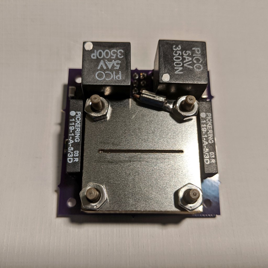
During the end of the second ignition test, I increased thruster emitter voltage, which increased emission output to the point of catastrophic arcing and failure between the extractor and emitter. Here we can see exactly where emission and eventual failure occurred on the underside of the extractor electrode, as well as the corresponding emitter corner and surrounding casing area.
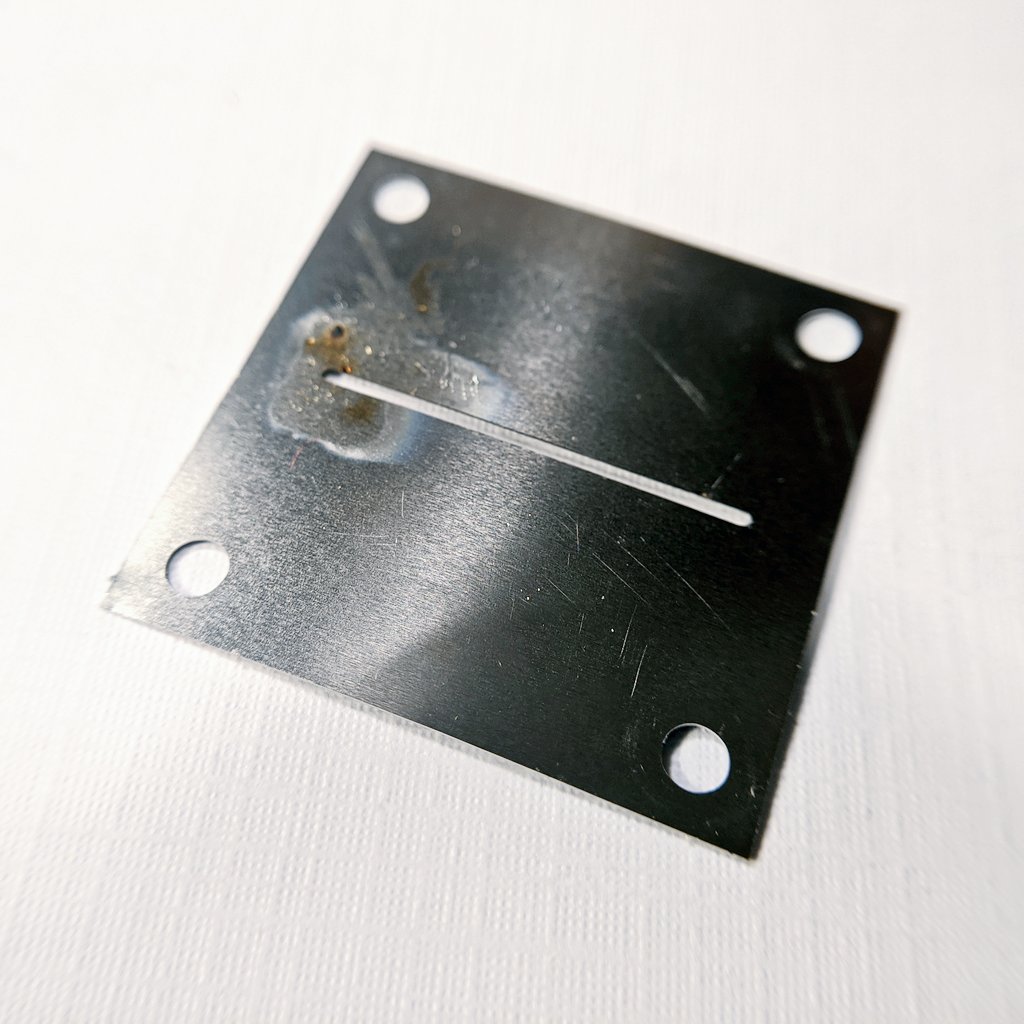
Let’s first take a closer look at the extractor. While I originally thought that a burr from laser cutting was the culprit of breakdown, it looks like the cuts were quite clean. Here we see where major arcing occurred resulting in carbonized fuel, leading to shorting.
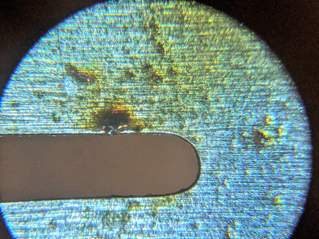
Zooming in to the primary arc point, we see a large deposit of carbonized fuel, the primary area where the fault started, later tracking it’s way across the thruster, where the second deposit clump was seen in the prior posted pictures.
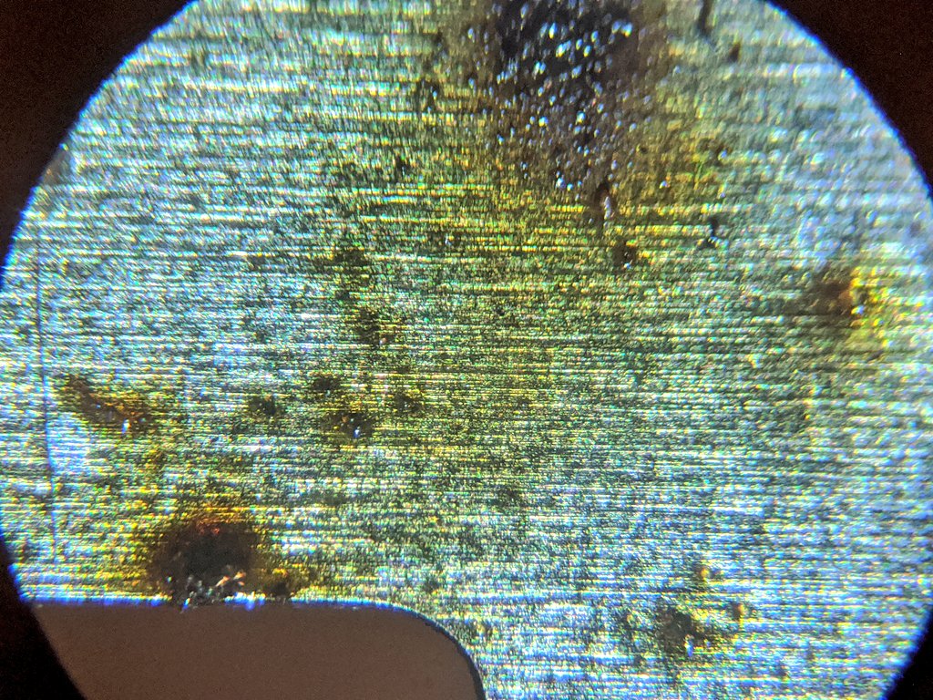
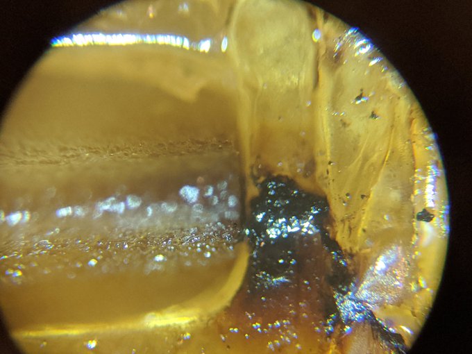
Moving along the extractor, we come across a very telltale sign of why the thruster failed. Droplets! What does this mean? That in this test, the ILIS1 was operating in mixed mode, emitting both droplets and ions, rather than pure ionic mode! This is very significant, and a major bane of ILIS tech.
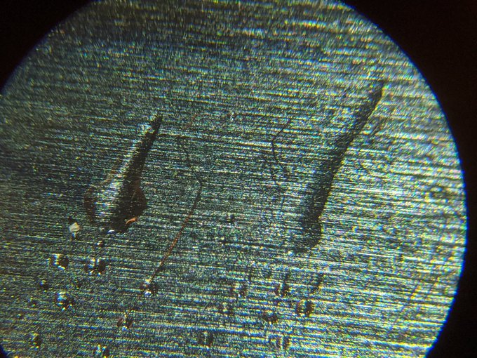
In literature most ILIS failure comes from shorting due to liquid deposit. As voltage is increased past the point of stable emission, significant beam divergence and extractor intercept can occur. This means many droplets now spraying onto the extractor causing buildup. As liquid builds up, it can bridge between the extractor and emitter. Being conductive fluid, arcing can occur, causing charring of the ionic fuel. This can happen very rapidly, and stop emission within a minute or two, as seen exactly in this case.
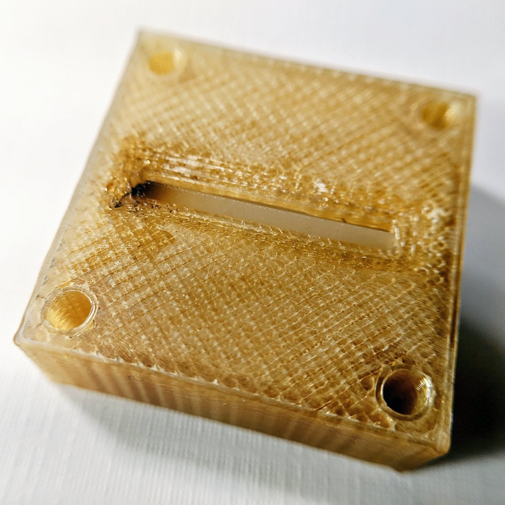
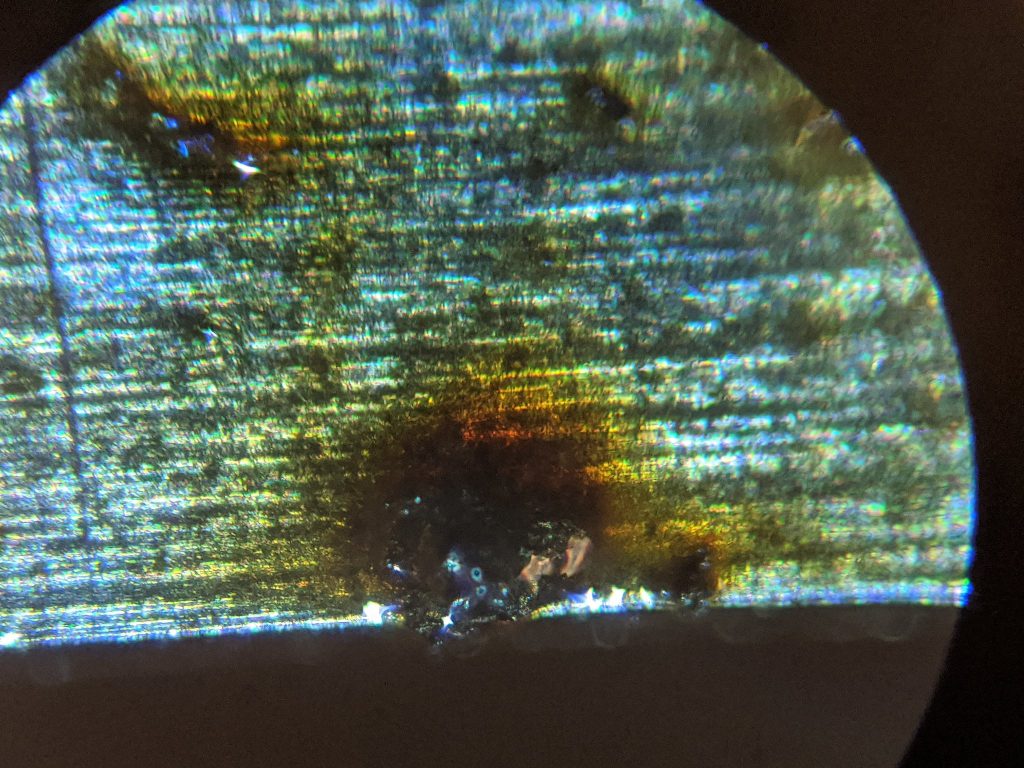
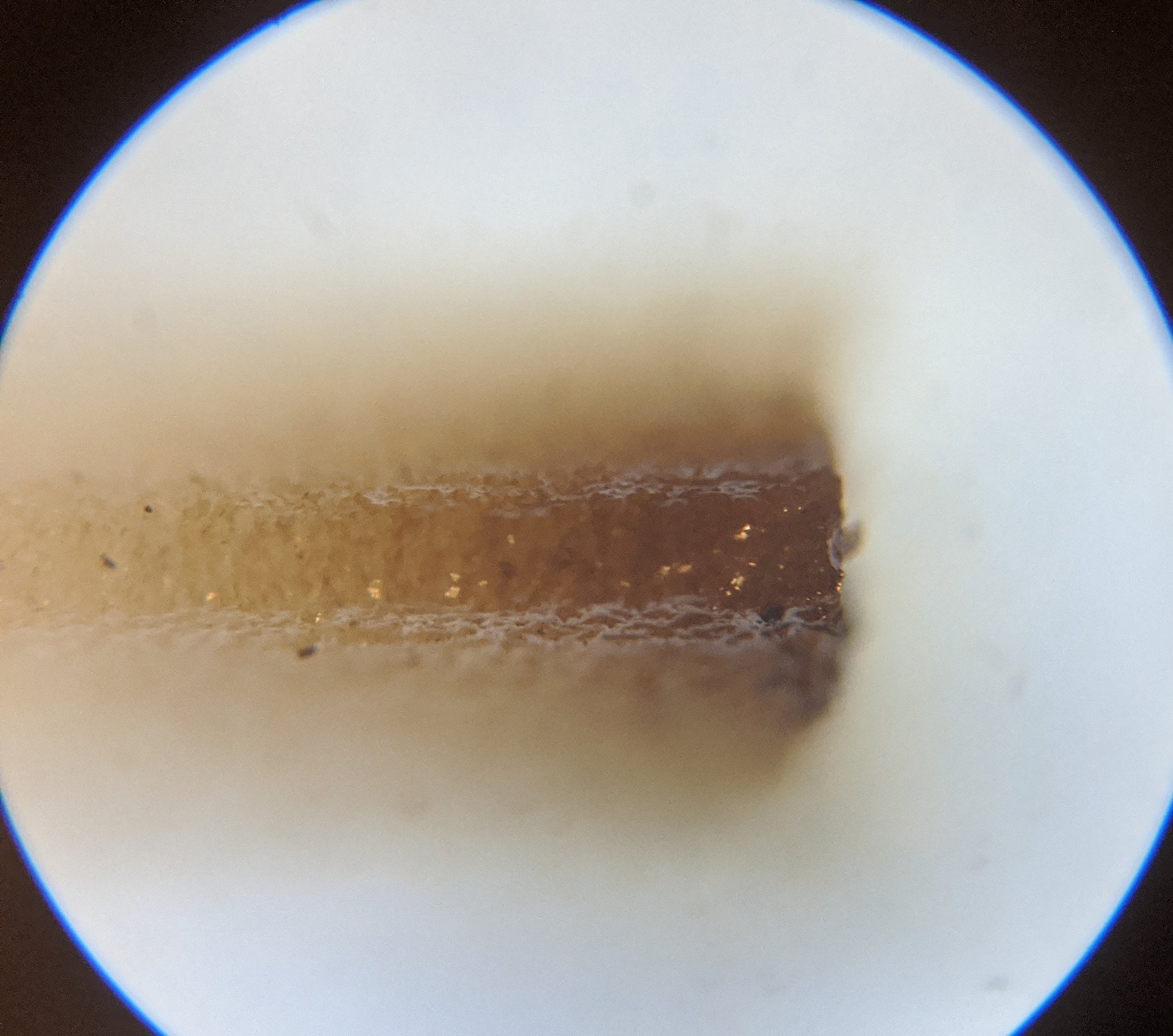
Now let’s move to the casing. Here we can see direct evidence of tracking due to this liquid bridging. A large clump of charred fuel is seen at the corner of the emitter, and a thin black snaking char line is seen, following the liquid as it conducted between pooled areas. Talking with others in the field, liquid bridging and ionic liquid creep on the non-conductive plastic cases used to house the emitter and reservoir remains as major challenges, and millions of dollars have been spent trying to mitigate this issue alone. Various liquid traps and creep-mitigating geometries have been explored for all types of ILIS.
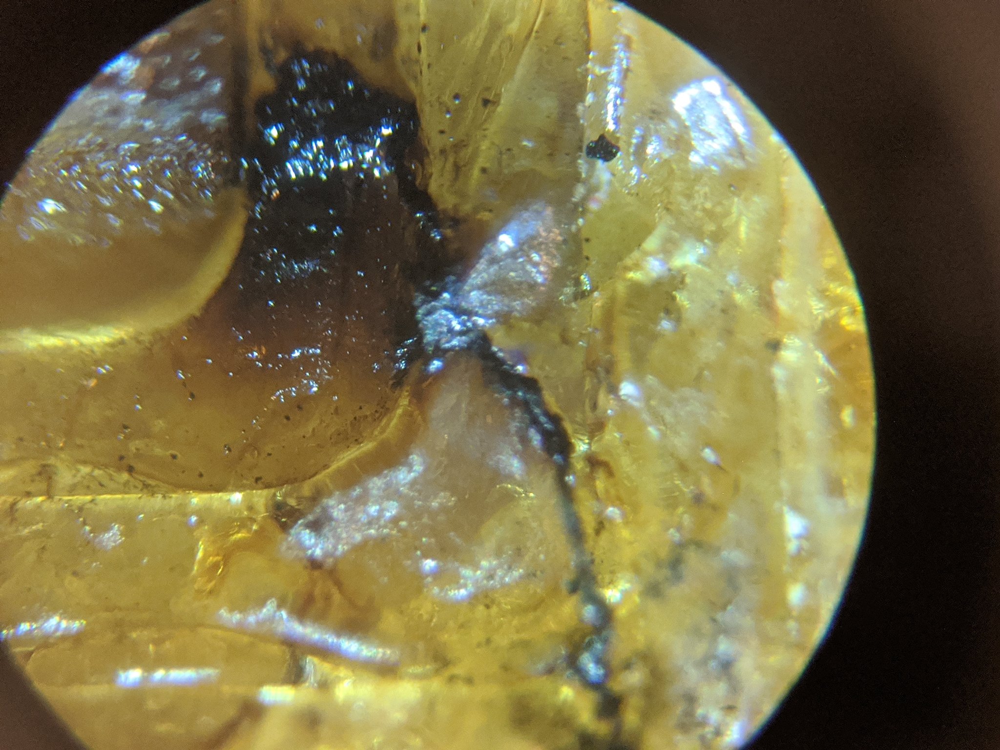
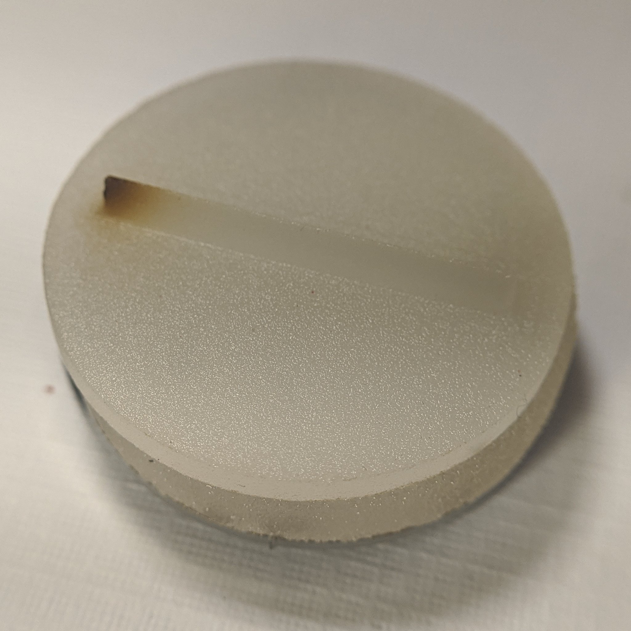
Now, we move on to the emitter. Here we can see a beautiful example of classic ILIS emitter damage. This can be seen regardless of micromachined or macro-scale ILIS, indicating damage of the emitter due to charring and deposit of the ionic liquid fuel
I went back and reviewed all the macro-ILIS literature I have collected to date. This test literally checked all the major boxes on key operational failure modes. This test was not much of a failure itself at all. In fact, I was able to established classic failure modes in mixed mode operation. In all the papers, only the best experimental results are presented. However, it takes many trials to get there. This was only attempt 2, and I am well on track towards getting a fully working ILIS thruster. As far as I am aware although the current literature has much better emission characterization, no one has ever made a fully integrated macro-ILIS thruster before, only using benchtop supplies for operating the thruster. This means I am closer to a deployable system than reported literature to date!
The main thing to tackle now is emission mode. While time of flight (ToF) to confirm emission species, it is very clear I am in mixed mode. Although colloidal and mixed mode offers higher thrust at lower ISP, liquid bridging failures are a direct result, greatly reducing lifetime. Why am I operating in mixed mode though? Fuel flow rate. Higher flow rate increases droplet emission. This is controlled by the selection of pore sizes for the emitter and extractor. Right now I am using slightly too large reservoir pores, allowing for a bit too high flow.
There is also a balance with voltage. As voltage increases past turn on, current rapidly rises almost exponentially, due to the emitter-extractor being an ion diode. Higher voltage also increases beam divergence, causing intercept, and in mixed mode this means fuel pooling. In mixed mode operation, higher voltage can also cause significantly increased droplet spray, compounding to operational issues rapidly.
In addition to all my prior posted improvements from testing, I will need to choke passive fuel flow by reducing the reservoir pore size. Also, by forcing the field gradient to be higher in the center versus the edges, I can avoid emission runaway at the tips as I increase voltage.
With all the improvements moving forward, I am confident I will achieve full stable emission soon. Once that occurs, then I will be able to move to the next phase of testing, characterizing lifetime. The ILIS1 is indeed rapidly moving forward!