In my previous post, I reviewed PART 1 of the first ever AIS-ILIS1 ionic liquid ion source electrospray thruster test, reviewing the fueling stage of the test. In this post, I review the actual ignition test, attempted right after fueling on July 4th, 2020.
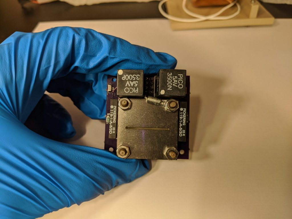
For the first time ever, I assembled the first fully fueled AIS-ILIS1 ionic liquid ion source electrospray thruster for nanosatellites! It was over a half a year ago in last October that I started thinking about the first possibilities of my own ILIS electrospray thruster. to see it finally come this far in such a short time from literally nothing is a major accomplishment in itself for this effort!
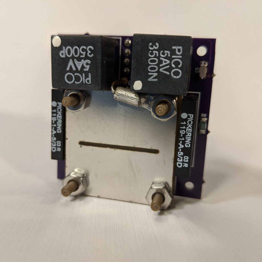
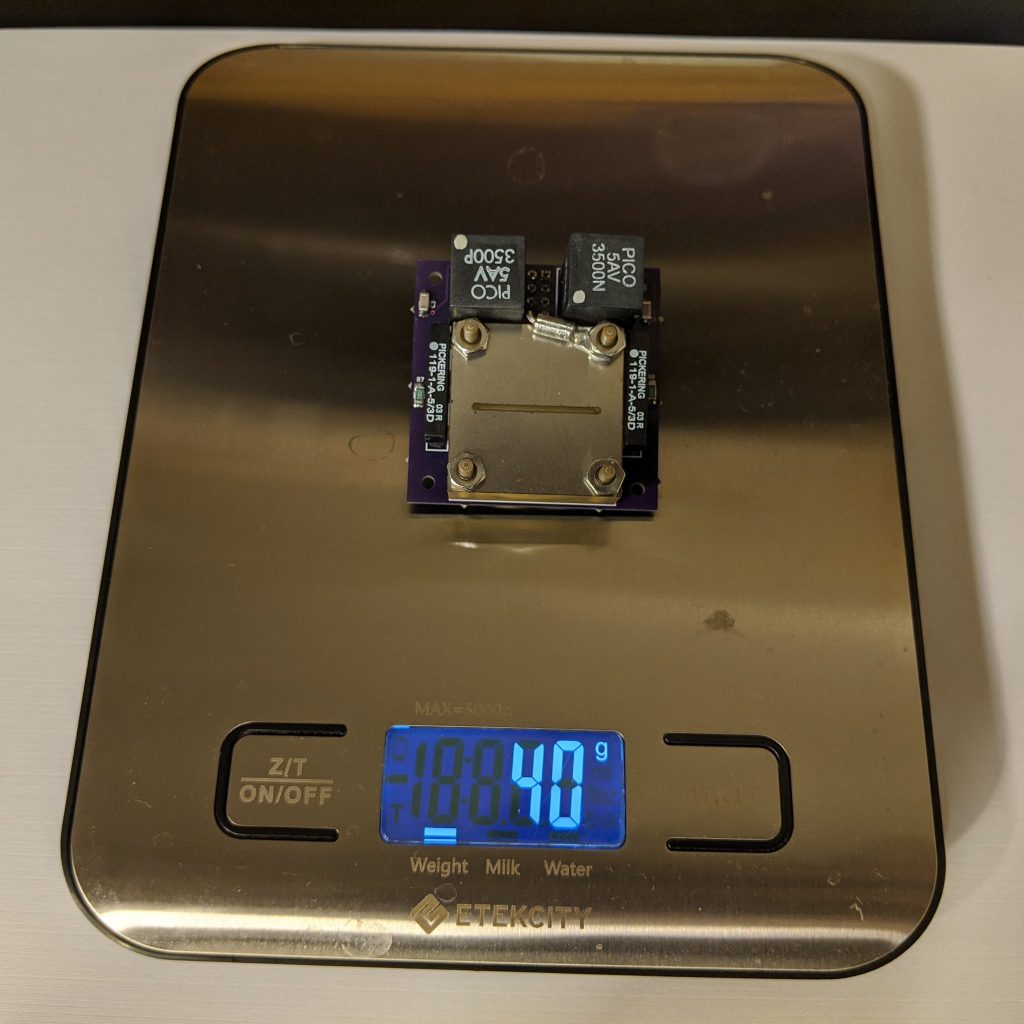
With the final assembly of the thruster with the reservoir and emitter loaded with degassed ionic liquid fuel, the final wet mass could be found. The final wet mass of the thruster is 40 grams, a difference of 1 gram from the dry mass found previously. However, operating in purely ionic mode of emission, that one gram can last hundreds of hours at several tens of micronewtons of thrust!
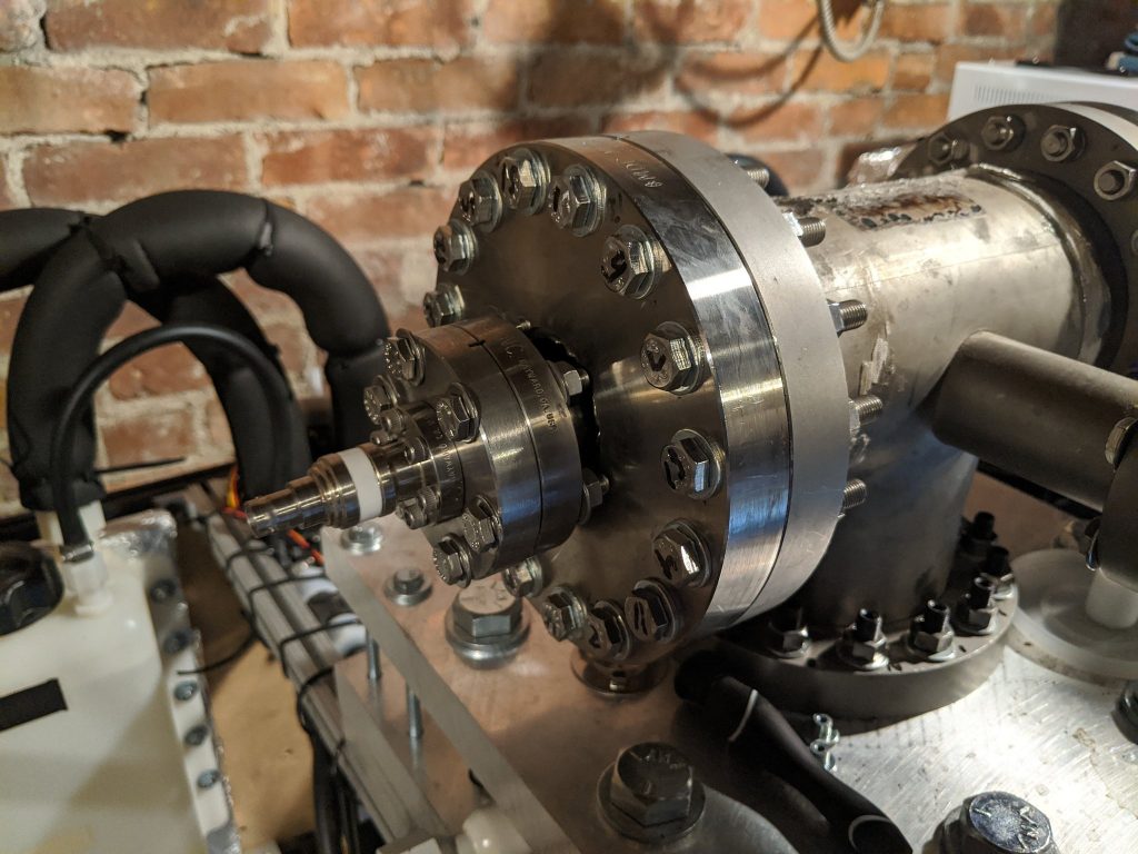
For size reference, the full thruster is only 45x45x16mm. If this works, it will be, as far as I am aware, the first ever PocketQube compatible ion thruster designed, built, and tested, in addition to opening up advanced ILIS electrospray technology for any nanosat team to afford!
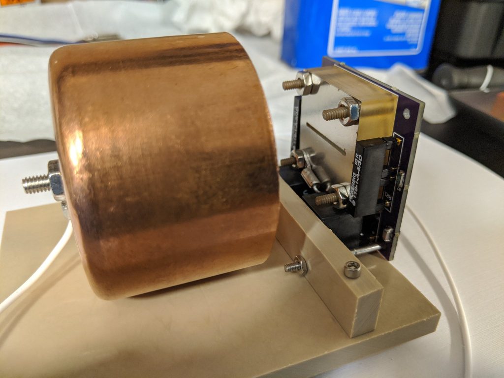
The thruster is now mounted to the Faraday cup test stand, which will be used to collect and measure beam current, verifying operation of the thruster, and giving initial estimates of thrust and ISP performance.
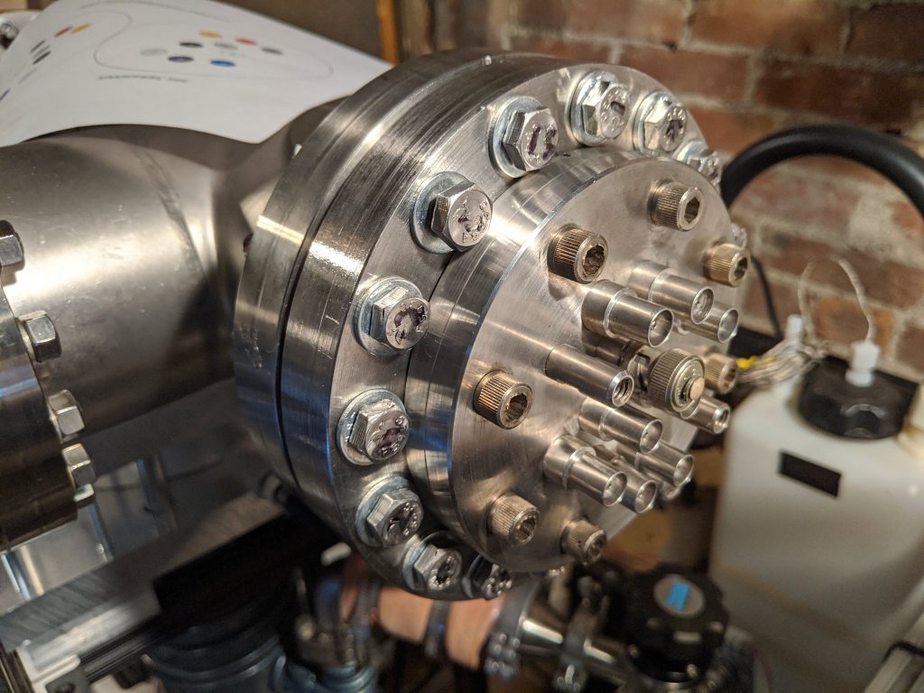
After mounting the thruster to the Faraday cup test stand, the vacuum feedthrough flanges were prepared for the test. On the left below, you can see the Faraday cup BNC output feedthrough. On the right, you can see the 9-pin feedthrough used for power and control of the thruster.
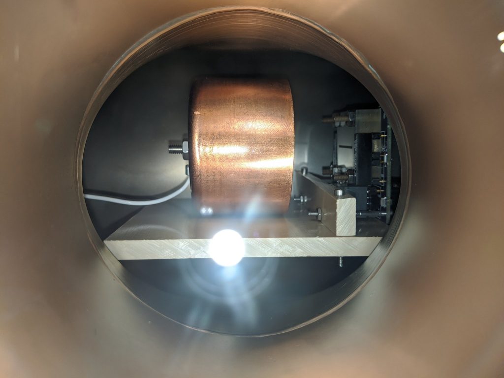
The thruster and Faraday cup stand are in place. With this angle, I can see if I can capture the very faint glow of the ion emission from the slit if it works. The system is sealed and ready to go. Time to start the pumpdown!
Over the next several hours, the system was pumped down to high vacuum before testing was started. At a vacuum of 2×10^-5 Torr, the first ever ignition of the thruster was attempted.
The first igntiion attempt was brutal. Try as I might, I could not get stable emission. A few blips of emission were possibly spotted and captured on video, however there were a lot of Arduino controller crashes, and lots of unusual board faults that were observed. At first, voltage could not be raised to over 850V, indicating a lot of conditioning would be needed. The voltage was eventually raised to several kV, and finally full voltage at +/-3.5kV, but still no emission. Eventually, the -HV supply failed.
Ultimately, the first ignition test was unsuccessful. I spent 13 hours fueling and prepping for the ignition test that day, and was utterly grueling. Despite this unsuccessful attempt, a tremendous amount was learned in the process. In the next post, i will review some findings of the post thruster test and disassembly of the system.