The other day, on July 4th, 2020, I attempted the first ever fueling and ignition of the AIS-ILIS1 ionic liquid electrospray thruster. Fueling started out rocky but ended up succeeding, however the ignition test was unsuccessful. In PART 1 I reviewed the fueling of the thruster, and in PART 2 I reviewed the setup and test overview. In this post, I will go over a more in depth analysis of the test, as well as steps moving forward.
Ignition attempts were started at 2×10^-5 Torr. The thruster control sequence started at 1Hz cycle, with thruster power slowly brought up. The Pico 3500P/N supplies turn on at about 2.5V, with a starting output around 800V.
For the first part of cycling, the thruster emitter voltage could not be raised above 850V without something causing the Arduino controller to glitch and trip. No arcing or visible faults were observed. This continued for several minutes, slowly pushing the voltage higher. Eventually higher voltage of several kV was established on the emitter, however faults continued to occur. The cycling time was switched to 0.5Hz, then 0.25Hz to allow more settling time at +/- voltages to help with conditioning and try to stabilize operation.
At this point there was some noticeable arcing occasionally on the board. It was difficult to tell, however it appeared on the back and at the bottom edge of the thruster. The voltage was slowly pushed higher to attempt to condition the thruster and start achieving emission. While no stable emission was achieved, there were a couple of instances of spurious emission, where the characteristic light bluish glow was seen from the extractor slit for a brief flash. This occurred only a couple of times, slamming on the full voltage during startup.
Towards the end of the test, the negative supply readout suddenly dropped to 0, with increased current draw from the power supply. No arcing was seen during the negative cycle, but it was clear that there was direct shorting somewhere on the board. It was during this time that a highly unusual observation was made. The positive cycle still achieved full voltage. However, the thruster block glowed dull red during each positive cycle. Not from heat, but something was ionizing in/near the clear amber 3D printed housing.
Upon disassembly of the thruster the biggest surprise was found – nothing. Absolutely nothing. No signs of arcing damage on the emitter or extractor. No liquid droplet spray between the emitter/extractor. No fluid leak. No burns, charring, or tracking along the board at all. In all my thruster testing to date there has always been some physical sign of arcing or damage that occurred at some point. Yet despite all the arcing I saw, there is no clear damage or tracking on the board or any of the components, and no issues with the fuel leaking.
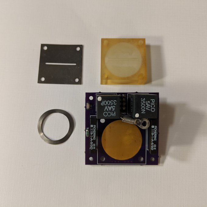
I will need to test the electronics with the high voltage test load and confirm why the negative side failed, as well as if there is arcing. I will also run some vacuum checks with just the board and plastic housing to see if the housing outgassing played a roll. Fortunately there was no damage to the emitter or evidence of arcing to it. The biggest issue of ILIS thruster lifetime is emitter degredation/damage. However, I strongly suspect that the 1mm aperture width was far too wide for field strength to be high enough for emission
Fortunately I also have 0.75 and 0.5 mm width extractors. While wider widths reduce liquid bridging, too wide and no emission will occur. Emission should have started in the 2kV range, but nothing happened even to 3.5kV. Key takeaways of the test include:
- Emission conditioning is needed.
- Faster cycle times is much more challenging for stability.
- Extractor aperture must be as small as possible while minimizing liquid bridging.
- Possible plastic outgassing from the housing is causing onboard ionization failures in the housing.
- High voltage with housing should be dry-tested in vacuum.
Going forward I will test the electronics, probably build a new board, run some vacuum tests with just the board, and switch to a much narrower aperture extractor. I will also start working out some better procedures for filling, degassing, baking, and sealing thruster parts.
In my next post, I will review some data that was collected and analyzed from what little video I could capture of the thruster.
This will definitely be a learning process. ILIS electrospray thrusters are among cutting edge micro-EP. Everyone else on the planet developing this has a budget of hundreds of thousands to millions of dollars with access to state of the art resources. I’m starting from the ground up at home!