I finally got around to finishing the preliminary electrostatic modeling for the ILIS1 thruster development a while ago. The main objectives for this study have been comparing my selected geometry to other macro-ILIS systems in literature to get an idea of field strengths, as well as figuring out the best dimensions for the extractor electrode. For the following simulation results, Poisson Superfish was used to set up the models and calculate the resulting field intensities for each of the geometries.
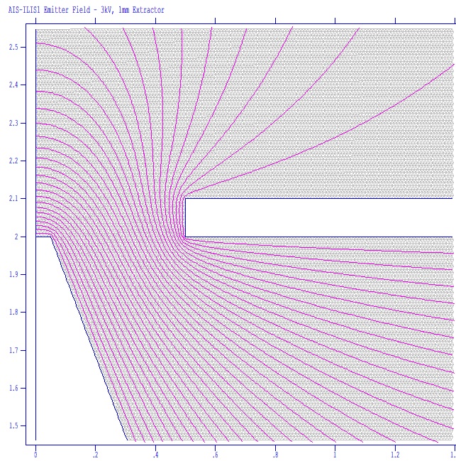
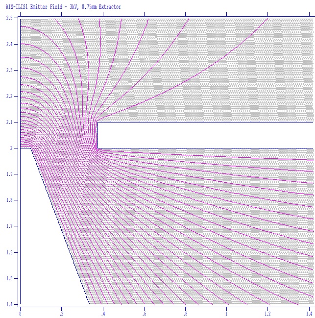
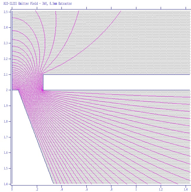
The first set of simulation results looks at various extractor slit widths for the ILIS1, ranging from (left to right) 1mm, 0.75mm, and 0.5mm respectively, with a 0.2mm extractor slit thickness. The emitter is kept the same for all of the models. This emitter design is the original set dimensions for the ILIS1, however the final actual machined version will be slightly different due to how the fabrication shop could account for tolerancing and the stock I provided them. The emitter tip is current set at 0.1mm wide, with a base of 2mm, and a total height of 2mm.
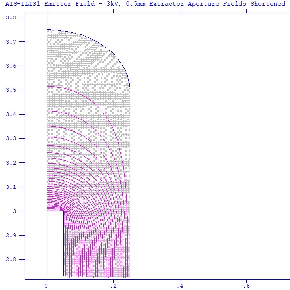
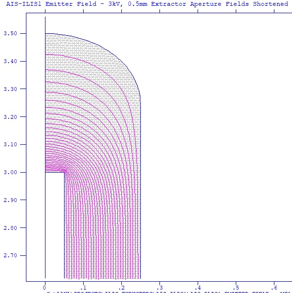
The emitter is slit based, as opposed to more conventional conical emitters often seen, and while I only have access to 2D modeling, I can at least get an idea of the fields by looking at various sections of the assembly. Here we see simulation results looking at the front of the emitter and the effect of slit end spacing. Having the extra space between the emitter edge and the edge of the slit aperture allows me to reduce excessive field enhancement at the sharp corners of the emitter edge, which would “turn-on” before the main surface and start emitting, and most likely be the area that breakdown would occur at higher accelerating voltages.
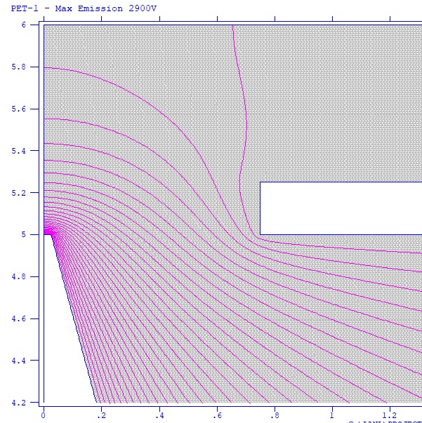
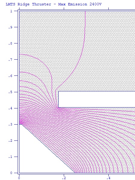
While it has taken a tremendous amount of digging and effort, fortunately there is enough info in literature to extract critical information and reverse engineer many thrusters out there. Here we have simulations from a few of the other various macro-ILIS thrusters in literature. The result on the left is the PET1 conical-based emitter. The right is the LMTS ridge-based emitter.
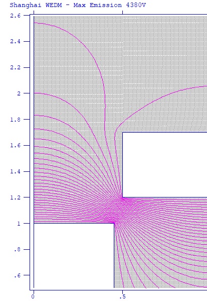
Finally we have a couple of interesting flat-edged emitters made from porous metals as opposed to porous glass like the prior posted ones above. The left result shows a flat needle-array based emitter, and the right shows a very interesting flat, ultra-wide-edge slit-based WEDM thruster design from Shanghai. Despite having a huge flat emitting surface of 0.9mm width, the thruster was still shown to fire!
Based on what I know now, moving forward I would change the dimensions of the glass emitter wedge slightly for the next iteration of the AIS-ILIS thrusters, to help increase field enhancement at the tip so that slightly lower working voltages can be used. The first set of emitters have already been in production for the past couple of months, however I won’t be expecting them back for a while due to manufacturing delays from the Coronavirus outbreak. This is not a major setback however, since it gives me plenty of time to continue troubleshooting and debugging the electronics, and to finish prepping the vacuum system for testing.

