I have been working on the V2 electronics for the AIS-ILIS1 ionic liquid electrospray thruster fairly intensively the past half week. The V2 revision included HV rated mosfets, as well as HV rated opto-isolated gate drivers, to see if I could solve the prior reported problem with the V1 electronics that the internal rectifiers in the supplies do not block against the opposite voltage (since both outputs are tied to the same load and are alternated on back and forth.) Despite my best efforts, the V2 circuit attempt was also unsuccessful. Even with 4.5kV mosfets and the 3.75kV VOM1271 HV-rated opto-isolated driver, I cannot isolate the supplies.
I have included the V2 circuit below for reference. There are still some components missing from it, such as the gate-source resistor for the mosfets. During the test, the 0.1uF decoupling caps on the low-voltage load switch side were not included. I also did not have a chance to test the newest addition to the circuit readout for diagnostics, which consists of the OPA2336 micropower op amp absolute value circuit to allow me to read both positive and negative polarity outputs into a single-ended supply microcontroller, like the Arduino that is used for testing.
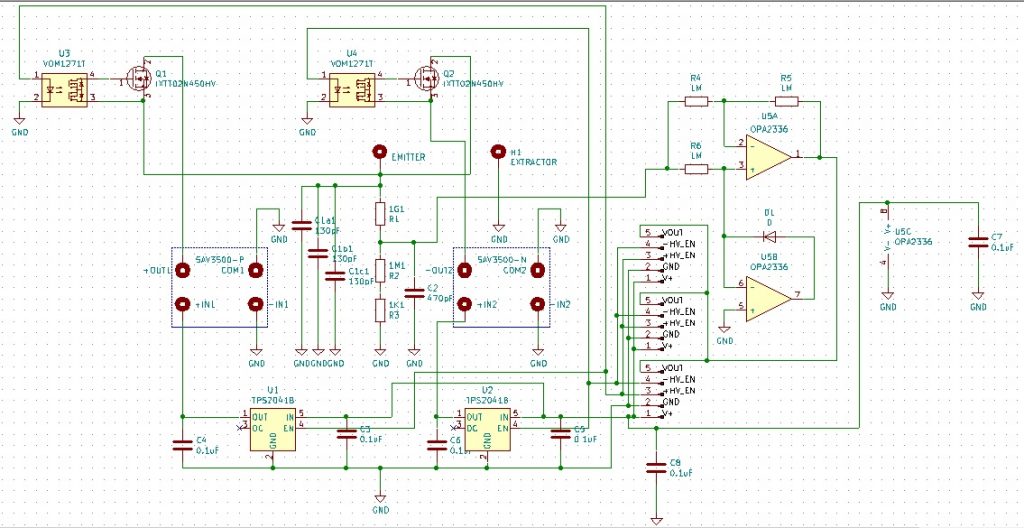
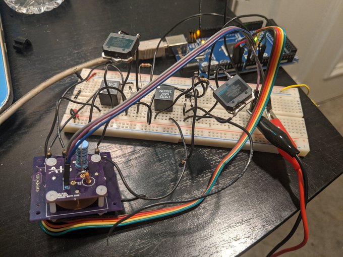
For prototyping the circuit, I was able to run testing with the V1 board and breadboarding the +/-3kV circuit without issue, as opposed to spending extra money and time on a new PCB. On their own, the mosfets provide isolation. However, as high side switches, even with a floating HV gate drive, they act as a short circuit and allow either supply to pass through. Each individual part of the circuit checks out fine, but together as a complete system it does not work. I am becoming increasingly convinced that for this application, semiconductor switching may not be possible, and that I might have no choice but to use mechanical means of isolation.
Finally, to rub salt into the wound, at the end of the testing, something critical failed on the V1 PCB itself. I don’t know if it’s the main HV filter cap or the readout resistors, but isolating everything and testing the supplies themselves on the V1 board I got high voltage running through the ground connections. Back to the drawing board.