Well, I have finally made the jump from live tweeting my propulsion tests on Twitter to actually live-streaming on Youtube! I have been looking to do this for a while now to give enthusiasts more direct and immediate access to actual electric propulsion testing real-time. This not only includes just firing the thrusters during the test, but full debugging and troubleshooting along the way. It allows enthusiasts to drop in and see what goes on during these tests, as well as gives a chance for open chat and discussion on propulsion systems and testing during the runs, and a unique opportunity to be there when things go wrong. Part of my philosophy for this open source propulsion development has been complete transparency. Regardless of what happens, whether an incredible breakthrough or catastrophic failure, I want everything reported, so that others can follow and learn. There is just as much, if not more to be learned from every failure, and indeed during this whole process I have made significant advances and improvements with each test.
Livestream Test 1 Overview and Thruster Debugging
The first livestream took place on September 30th, 2019. This test was part of the first lifetime qualification testing for the Fossa Systems joint collaboration mission, testing and qualifying the new AIS-gPPT3-1C V3 boards. A link to the YouTube video can be found here:
AIS-gPPT3-1C Pulsed Plasma Thruster Livestream Lifetime Test #1
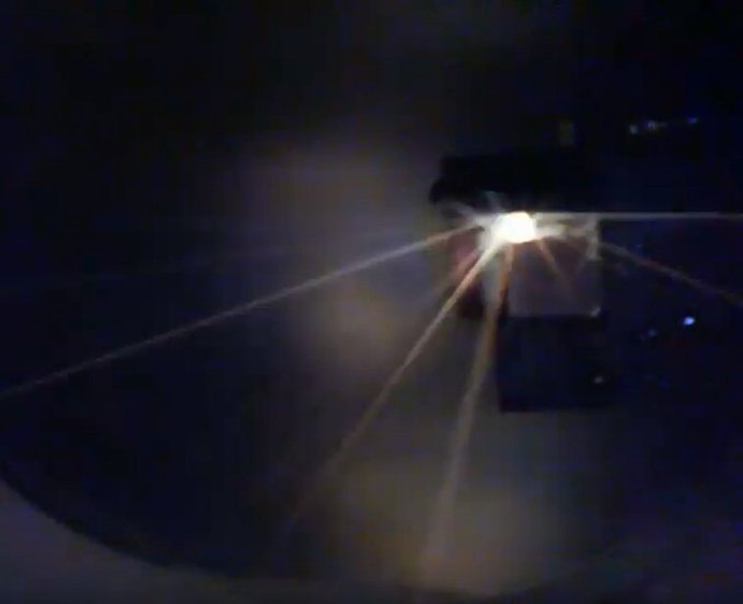
Unfortunately, I didn’t achieve stable ignition until about 1.5 hours in, but it was a great chance to engage in some live thruster debugging. The total test ran about 2 hours. For the first 1.5 hours, ignition was quite erratic. While each firing corresponded with a trigger command, there were mostly misfires. After the first hour of testing, there were about 200 shots. Various rep rates and trigger widths were tried. At around 1:26:00 in the video, we can see the start of stable and repeated ignition. Rep rate at this point is about 0.25Hz. This was only after the input was boosted from the nominal 3.3V to the max of 5V. This ran smoothly with almost no misfires until about 1:52:00. Unfortunately this higher voltage required over-driving the pulse caps, despite very stable operation. At 1:52:10 one of the main pulse caps failed catastrophically, blowing out debris from the side of the casing. Here you can see a captured shot of the failure from the video:
The total recorded pulses for the V3 module up until this point was at 736. The original V1 survived 130 (which was covered during the first impulse bit test of the new thruster module). This is a big improvement, but still a long way to go. Overall, the gPPT3 thruster stack itself (the copper and Teflon pieces that make up the thruster) had clocked 866 pulses total. The prior gPPT2 stack lasted 500 pulses at higher energy before charring.
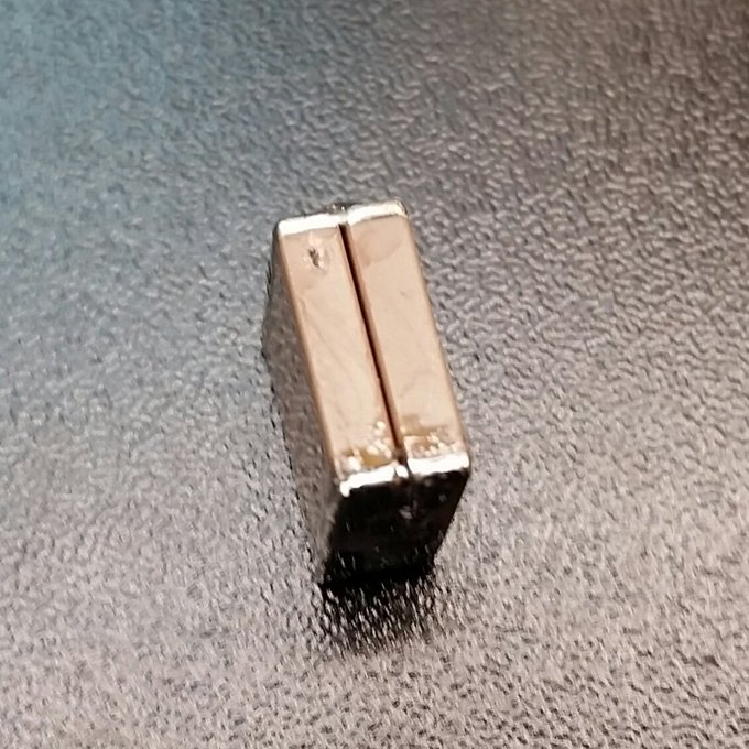
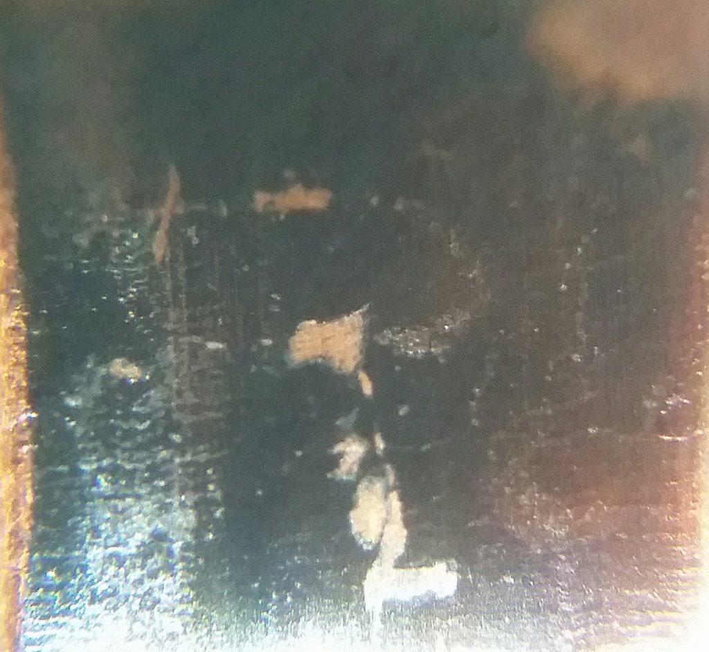
After this test, it was time to take apart and troubleshoot the thruster. First, let’s start with the blown cap. In the left cap at the top, we can see a small hole where the pulse blew through the case. Failure occurred at pulse 736. Caps were at max charging voltage of 2kv, for a total bank energy of 0.27J during the failure. Although the caps are rated for 2kv max short term, they should be operated around 1kV, and were at a much higher energy than the nominal spec of 0.06J.
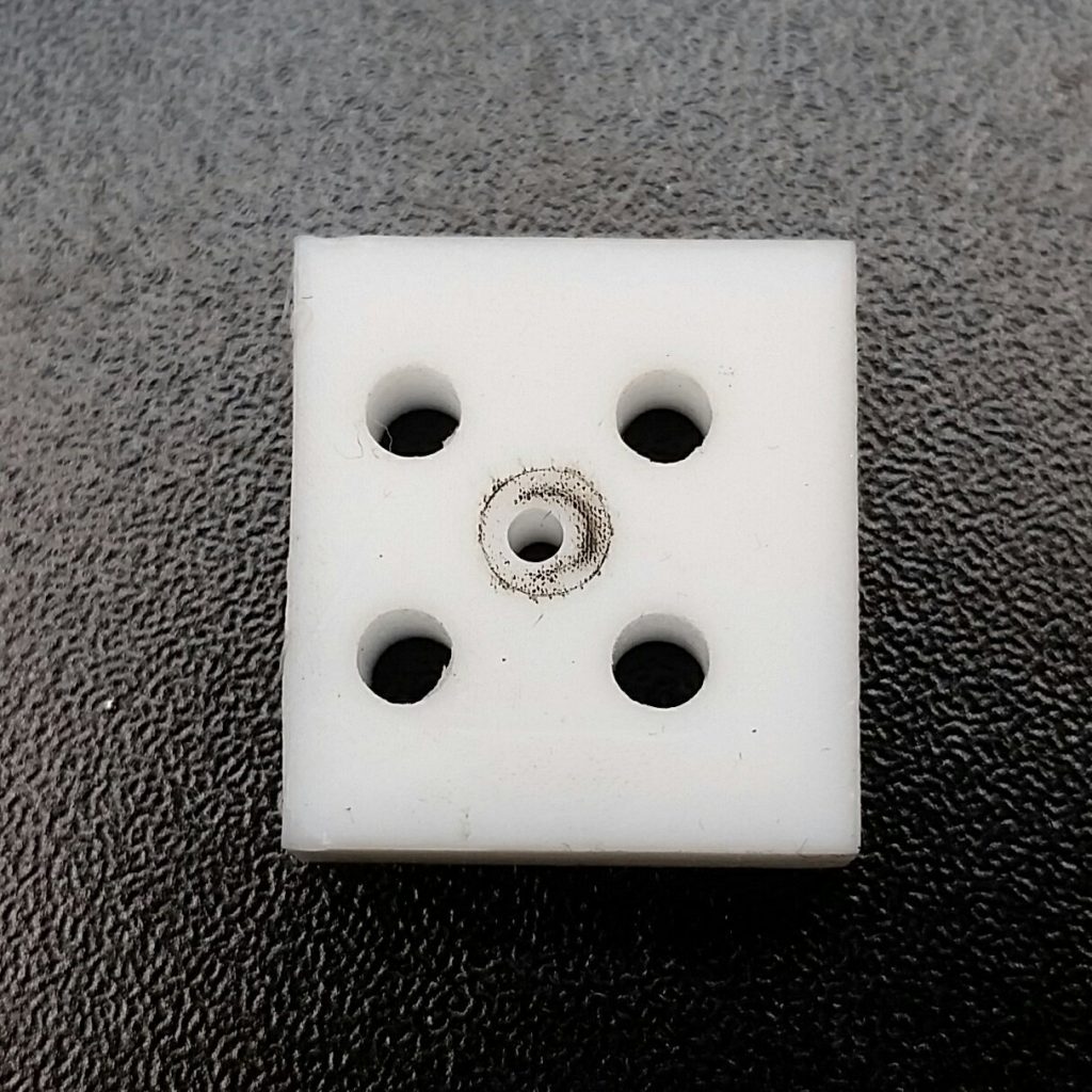
Next we will look at the fuel bore, the area of primary concern. After 866 total shots from 0.06 to 0.27J, there is no fuel charring or wear in the bore. Only some light very light sputtering on the back facing the igniter, which would have no impact on performance. Even measuring with calipers, there was no change in diameter. Originally I thought the issue was somehow failure to ignite the fuel due to depletion or difficulty ablating at low ignition levels. Apparently though, this is not the case at all. The fuel was fully intact, and hasn’t even shown signs of really being used yet!

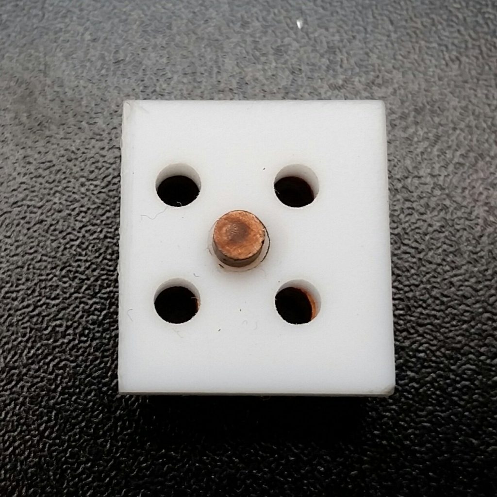
This leaves one culprit left: the igniter-cathode interface. Here we see signs of very uniform discoloration on both electrodes in the ignition area. Minimal at the end where the main discharge occurs. Towards the rear, there is a deep red band, which fades to black to the front. My thoughts are that this buildup over time, coupled with the relatively smooth and larger uniform ignition surface area, causes the igniter pulse difficulty arcing over in vacuum. The bank fires, but does not mean that a vacuum arc has been initiated. At the higher igniter bank voltage and energy with 5V in, issues of ignition reliability due to buildup are overcome, at the expense of the main cap bank lifetime. At the lower anticipated input voltage of 3.3V however, this causes some issue over time. Fortunately, this is great news, with several options going forward. Increase igniter bank voltage (via 1 resistor change), and/or change electrodes with a geometry that increases field enhancement (aka sharper features). Other metals for the cathode pin or igniter could be explored as well.


Livestream Test 2 Overview and Thruster Debugging
After reassembling the thruster stack and soldering new pulse capacitors, I was ready for the second phase of lifetime testing on the thruster. This test occurred on October 3rd, 2019. A link to the full testing video can be found here:
AIS-gPPT3-1C Pulsed Plasma Thruster Livestream Lifetime Test #2
The goal of the test was to simulate more realistic run cycles that the thruster would see in orbit. Based on the mission specifications, the thruster would be fired for 15 minutes straight once every 90 minute orbit. So the thruster would be on ideally for 15 minutes, then off for 75. In order to speed up this process however, I opted for a 5 minute cool-down period between firings. In addition, the thruster would be tested at 4V in, which would be the direct battery bus voltage from the PocketQube. this would hopefully provide enough voltage for ignition, greater than the initial test at 3.3V, but not enough to drastically overdrive the capacitors like with 5V in.
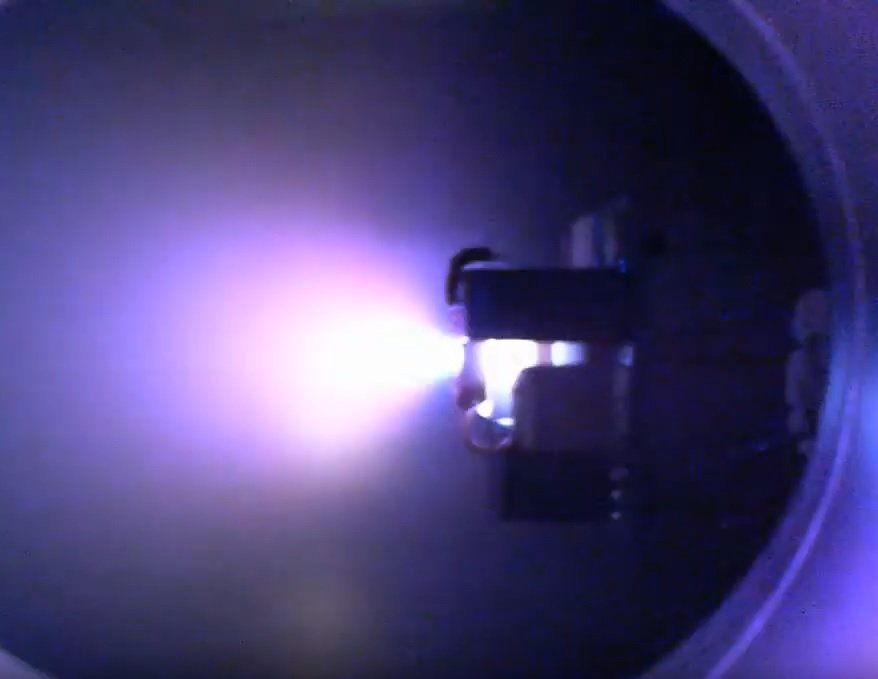
The thruster ended up successfully completing x5.33 15 minute orbital firing cycles with 5 minute cooldowns in between, before the main bank shorted and failed again. The repetition rate was between 0.29-0.33 Hz for the 15 minute cycle duration. Input voltage was kept at 4V for the duration of the test. A total of 1232 shots were counted during this test, which was the highest shot number yet for a test! In addition, the lower and upper bounds for successful ignitions was between 78-91%. For the 15 minute cycles, total ignitions were very repeatable, at around 220-240 per cycle. Below is a captured plume from ignition on the webcam (much lower quality than my normal phone pictures):
At 4V in, the peak current draw during the start of each charging cycle was found to be around 150mA, for a peak module power of 600mW. Standby current draw was around 90mA, for a standby power of 360mW. Shot energy was around the 0.15J range per shot. Although the main bank died, it was confirmed that reasonably reliable ignition can be achieved with the designated 4V bus input from the battery supply, even after several thousand shots. Upon inspection of the thruster, no noticeable change in electrode buildup was observed. In addition, the Teflon fuel still has absolutely no charring in the bore, and no measurable change in diameter. Total shots to date on the board (minus the cap) and thruster stack is now confirmed to be 2098 shots. Still orders of magnitude lower than the final goal, but its a start on the journey for sure!
Conclusion and Moving Forward
It has is now very clear that the sole bottleneck for lifetime at this point is the main discharge cap. Reducing voltage allows for more shots, but still fails well below the projected total fuel lifetime of 100k shots. Fuel and electrode erosion at this point are not factors. Reliable ignition can be achieved however by increasing the igniter bank voltage, which does not appear to affect the igniter cap longevity, due to the significantly lower pulse current it delivers. This is easy to do with a single resistor value change on the board. Going forward, the key will be obtaining high lifetime vacuum rated pulse caps. The circuit will also be adjusted to boost ignition voltage, as well as looking to increase rep rate to at least 0.5Hz with 80% ignition reliability. So far, each test has been a great step forward!