INTRODUCTION
In the previous two DIY Science series projects, I covered the basics of gliding arc discharges, a type of atmospheric nonthermal plasma. In the first project, DIY Handheld Gliding Arc Discharge Plasma Surface Treater, a major overview of gliding arcs was presented, as well as a walkthrough on how to build a simple low-power handheld demo unit from common parts and materials, and explored simple experiment examples of surface activation using the contact angle test with water. In the second project, DIY High Power Gliding Arc Discharge Plasma Treater, a more powerful system was built that could handle several kWs and allow for more intensive and large-scale treatment of surfaces, as well as difficult to activate surfaces such as Teflon. This system, like the first, was also constructed with very simple and extremely low-cost materials. Here, we explored surface activation through the ink streak test. In this next project, we will be exploring a more advanced topology of gliding arc discharge utilizing vortex stabilization. Before diving into this more advanced system, I would strongly advise looking over the previous two systems first to get a better familiarity and introduction to gliding arc discharge technology, since this system also utilizes a high-power arc.
VORTEX STABILIZED GLIDING ARC OVERVIEW
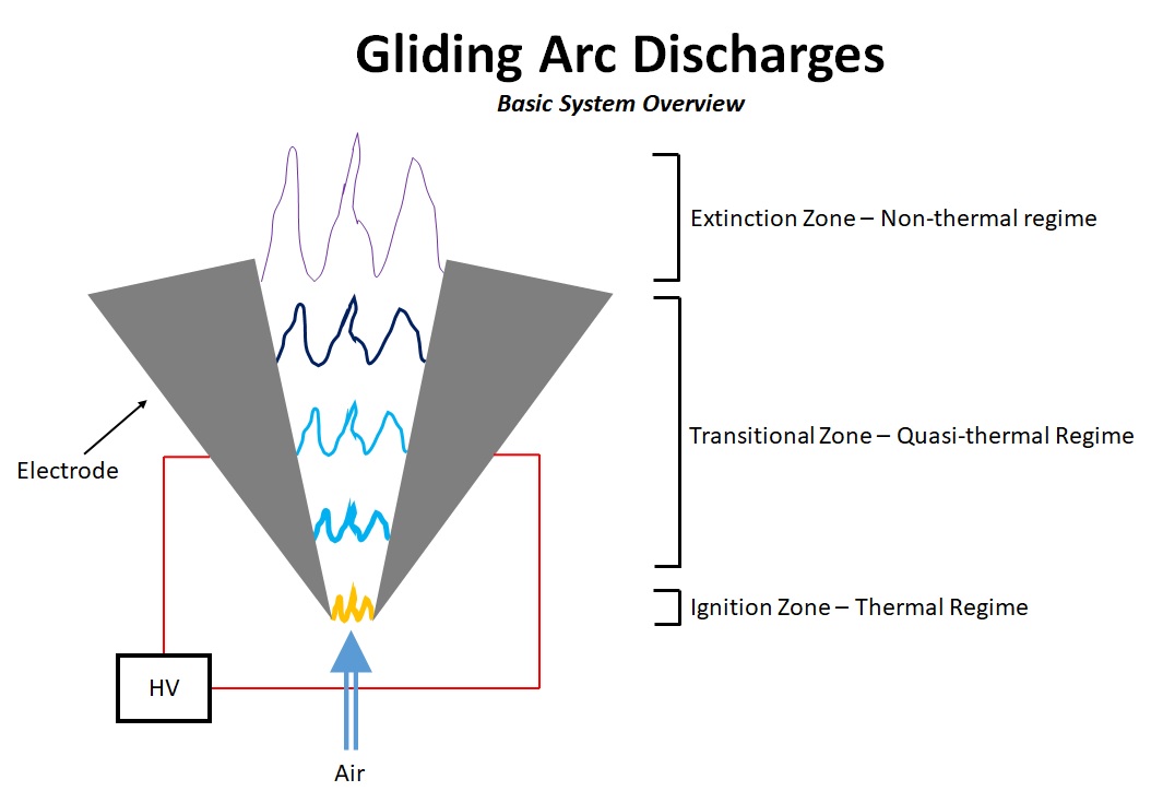
For the previous two systems, the most basic and common topology for gliding arc discharges was employed. This discharge consists of a planar discharge over two diverging electrodes with the process gas (usually air) blown between the electrodes linearly and pushing the arc forward. Essentially, it is a modified Jacob’s ladder with air assist. A basic diagram of this topology can be seen below:
However, this is not the only way of generating gliding arcs. A second major method is to instead use a coaxial geometry, with an inner and outer cylindrical electrode. The electrodes can diverge or converge using tapered geometries such as nozzles or sharpened cylinders, but this is not always required. An additional variation is to use two co-linear cylinders as electrodes, with the arc rotating between the edges of the electrodes.
Vortex stabilization takes advantage of the cylindrical geometry, and instead of blowing air directly between the two electrodes to force the arc straight out, it is injected tangentially to create a swirl of air inside the system. This vortex forces the arc to rotate about its central axis while simultaneously being pushed forward. There are several key advantages for this type of system that makes vortex stabilized gliding arc particularly well suited for applications such as hydrocarbon reforming, gas processing, and plasma assisted combustion.
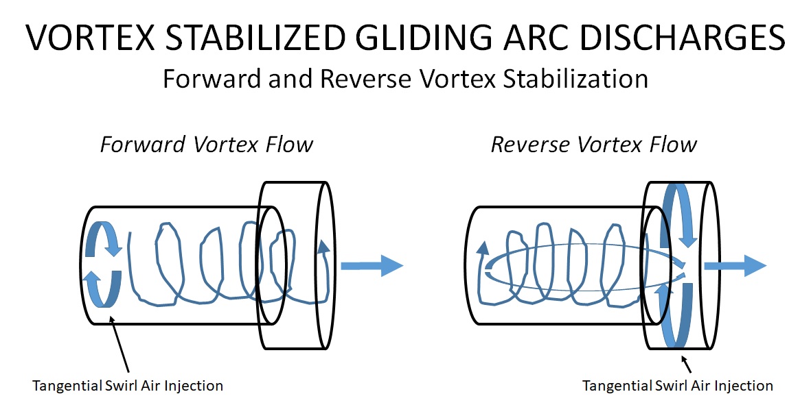
Within the category of vortex stabilized arcs, there are two methods for air injection, and thus stabilization: forward flow stabilization, and reverse flow stabilization. In forward flow, air is tangentially injected at the back of the device behind the arc, where it travels up the body and pushes the arc out directly. In reverse vortex stabilization however, air is injected at the front of the device, either at or after the point of arc ignition. The air creates a vortex which first spirals towards the back of the device, then reverses on itself and flows back out towards the nozzle. Reverse flow stabilization has advantages of increased stabilization as well as much more reaction area between the arc and the process has, but at a slightly higher expense in complexity. For this project, forward vortex stabilization is employed.
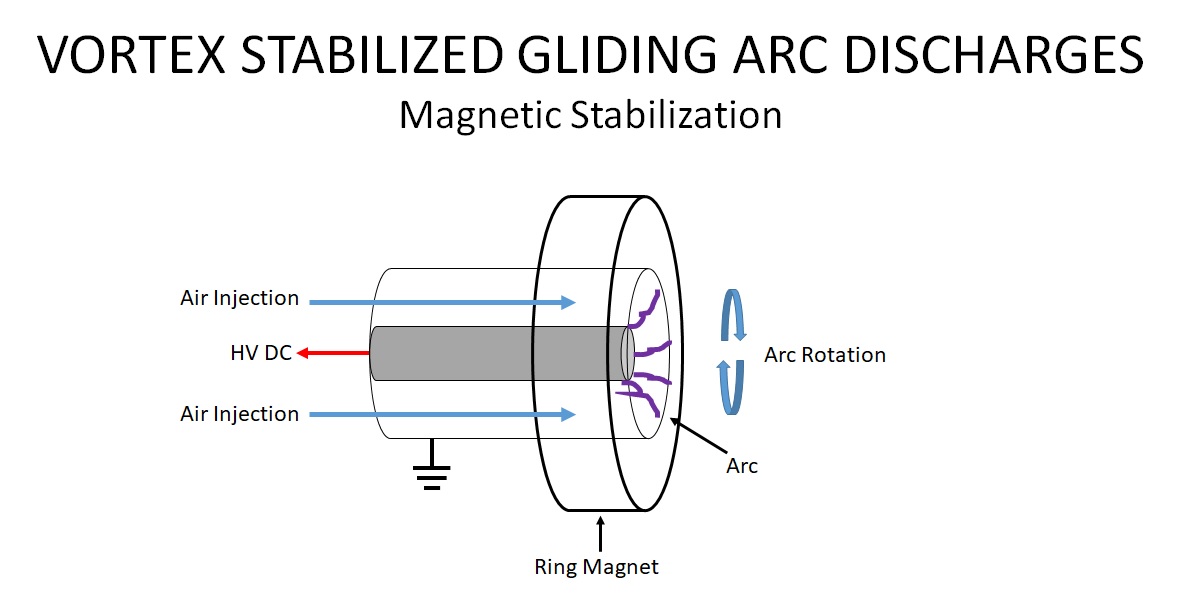
There are additional methods of stabilization that can be employed as well. For DC plasmas, ring magnets can be utilized to induce rotation about the central axis due to the magnetic field, as well as setting the arc position. Using a movable ring magnet, or DC magnetic coils, arc position along the length of the electrode can be adjusted. Straight air injection and tangential air injection can be employed with this method.
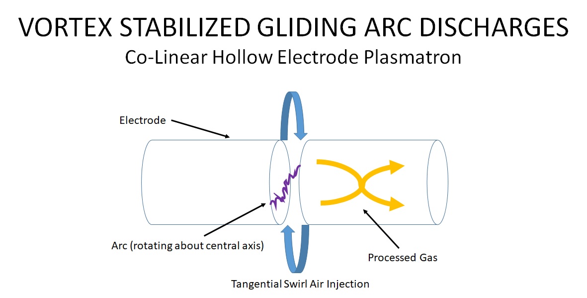
An additional type of plasmatron topology utilizes co-linear hollow tube electrodes, where the arc is struck in the space separating the electrodes, and tangential air is swirled in to rotate the arc along the edges. This topology is mainly used for gas processing and hydrocarbon reforming. For the project build described below, we will only be focusing on a forward vortex stabilized gliding arc discharge.
PROJECT BUILD
For this simplified vortex stabilized gliding arc discharge, I used several pieces of scrap hardware that was lying around. This was just built quick and dirty to provide a basic experimental demo, and there are countless ways to go about building such a system. The basic build can be seen below:
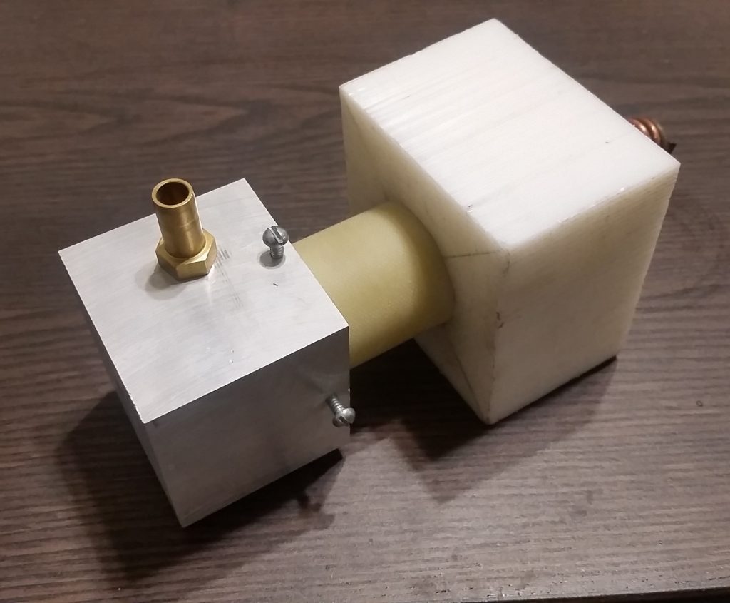
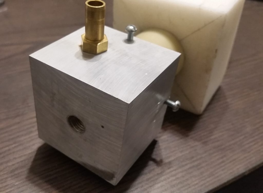
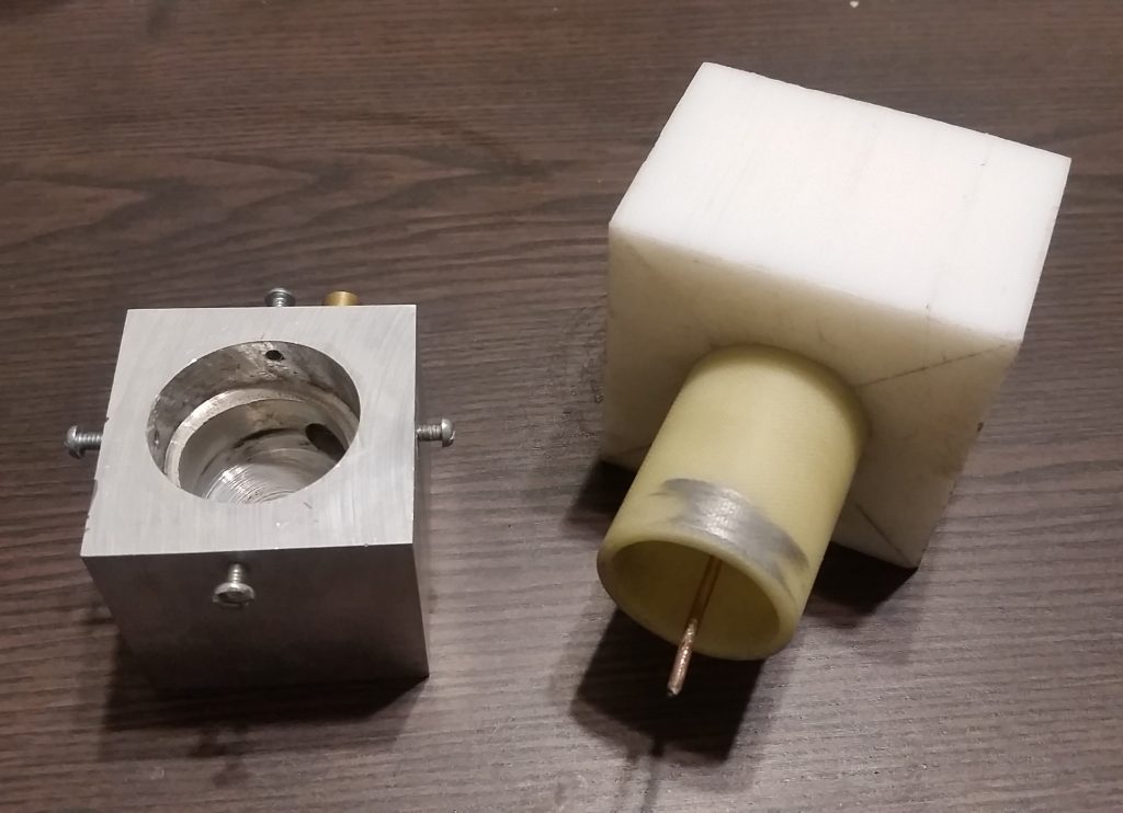
The construction is still incredibly simple, though requires access to a drill press and some large drill bits. The front electrode is made from a block of scrap aluminum, which was bored out with successively large drill bits to tightly fit the plastic tube-body. The front electrode also includes the single port for the tangential air inlet injection, tapped for a common NPT to hose adapter. The outlet is also tapped to accommodate a nozzle made from a slightly larger-sized NPT to hose fitting, with the inside drilled out for a larger internal nozzle diameter. Four small screws are located around the edges of the electrode to clamp the body to the electrode. While it first appears that this is in the form of a revers-vortex stabilized system, the airflow injection is not actually set up properly for a reverse vortex, and just pushes the arc forward (since the air injection is still behind where the arc forms, rather than directly at or in front of it for true reverse-vortex stabilization.)
The back end of the body consists of a short section of plastic tubing fit into a block of plastic, drilled to the same diameter as the front electrode bore. A small hole in the center is then drilled to feed a 1/16″ thick copper wire through to serve as the coaxial electrode. Spacing between the two electrodes is adjusted by moving this wire electrode in and out, either closer to or further from the output of the front electrode.
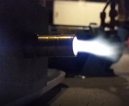
The system can be run on any process gas, as well as either AC or DC. For the following tests, straight HV AC from a ballasted dual-MOT supply at 1kW, 4kV is used with air. A couple of test shots are shown of the resulting plasma, depending on operational mode. A noticeable difference in the arc can be observed between the system run without an output nozzle (left) and with an output nozzle (right). Actual run videos can be seen in the next following sections.
DEMO 1 – VORTEX STABILIZATION WITH NO OUTPUT NOZZLE
In this first demo video, we will have an opportunity to actually see the vortex stabilized arc in action. This demo is also done without the output nozzle, for two reasons. In this configuration, we can better see the rotation of the arc due to the tangential air injection. However, from an operational standpoint, the characteristics of the arc also changes. With a direct and open output, the arc is allowed to expand further, allowing it to operate in a much more nonthermal regime. However, with an output nozzle that constricts the plasma and gas flow, the arc enters a quasi-thermal regime, which appears as a more concentrated and intense discharge.
In the video, two views of the system during operation are shown. This first view shows the arc from the side, where you can see the expansion length of the arc in the nonthermal region. In the second view, the video shows operation straight into the device from the front, where you can clearly see rotation of the arc due to the tangential airflow. The system utilize the same 1kW AC dual-MOT power supply as introduced from the previous high-powered planar discharge system.
DEMO 2 – VORTEX STABILIZATION WITH OUTPUT NOZZLE
In this next demo video, we see what happens when we add an output nozzle to concentrate the discharge. As previously discussed, with the addition of the nozzle, the arc becomes more constricted and concentrated, raising the discharge to a more quasi-thermal regime (though still operating as a nonthermal plasma).
GOING FURTHER
Now that we have established a method of creating an incredibly simple vortex stabilized gliding arc discharge, with a couple of different modes of operation, where can we go from here? Like the previous gliding arc builds, this system can also be used for materials science, surface modification, and surface activation. In particular, such systems, especially the concentrated arc with the output nozzle, can be used for rapid activation of precise areas. This is often seen in industry activating edges for gluing, or thin cross-section parts rapidly, and offers a good in-between activation method in terms of speed and aggressiveness between more nonthermal gliding arc, and flame treatment.
The system can also be greatly improved upon and expanded. This was a simple demonstration using scraps, but a fully engineered system can easily be designed and built as well. Various topologies can also be explored, such as magnetic stabilization, reverse flow stabilization, and co-linear tube-electrode plasmatron topologies. This in particular leads to some very exciting experiments with plasma assisted combustion. In the next DIY Science build, I will be demonstrating this exact system for plasma assisted combustion experiments, for use as a simple plasma-assisted fuel nozzle burner with propane, exploring some of the dynamics of the system and how stable burn can be achieved under operating conditions where a flame could not be normally ignited or sustained. From this example, a more engineered system will be designed and built as a full tabletop demo burner for exploring advanced combustion sciences as well as gas reforming. This system will include control via Arduino and MegunoLink software, as well as sensors for studying system outputs such as CO reduction and flame temperature.