INTRODUCTION
In the previously posted DIY Handheld Gliding Arc Discharge Plasma Surface Treater, we explored the basic principles and overview of atmospheric non-thermal gliding arc discharge plasma technology. In this DIY Science segment, we will be looking at a much more high power, large scale gliding arc plasma treater for more advanced studies of surface activation and modification using atmospheric plasma technology. This system allows one to not only treat larger scale surfaces faster, but allows for better activation of more difficult plastics such as Teflon. This plasma treater is made from common supplies and scrap hardware for almost no cost, and can be powered by a wide variety of high voltage supplies, either AC or DC, from several hundred watts to several kWs.
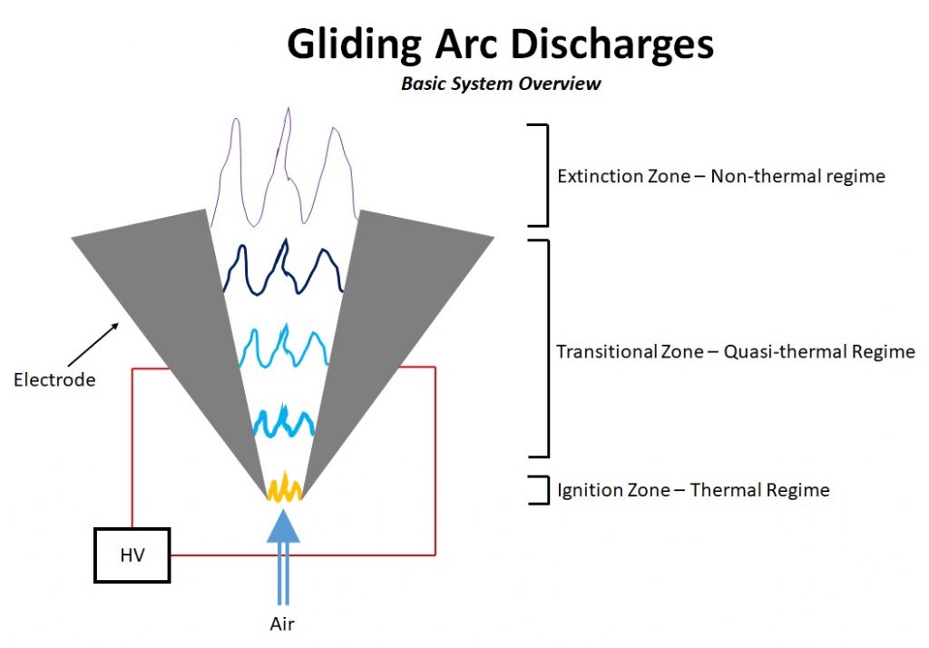
GLIDING ARC DISCHARGE OVERVIEW
In the prevously mentioned post for the low-power hand held system, we reviewed the basic principles of gliding arc discharges. For reference, the basic topology of this system is as follows (a full explanation can be viewed in the DIY Handheld Gliding Arc Discharge Plasma Surface Treater build walkthrough, and is highly recommended to review this information first before proceeding to the more high power and dangerous version):
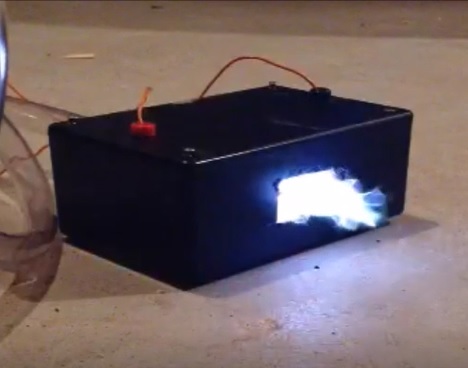
As opposed to the handheld version, the high power version is actually much simpler to build. Some snapshots of the DIY plasma treater are shown below:
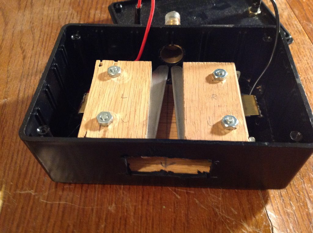
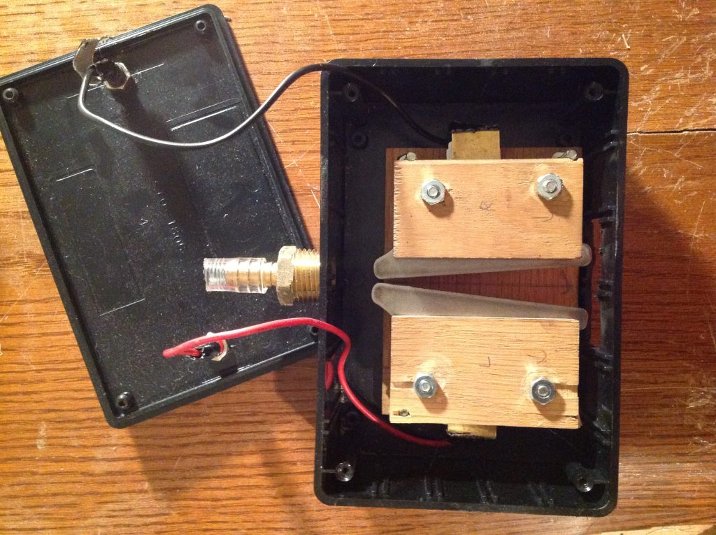
The electrodes were made from some random pieces of flat rounded-edge steel plates I found, about 1/16″ thick. These plates are sandwiched in between a couple of pieces of plywood and plastic, held in position by tightening the bolts to compress the assembly. The ignition zone is adjusted to be very close to allow for easy ignition, and centered right in front of the brass hose adapter air inlet. The end of the electrodes are spaced wider to create a divergence, resulting in a wider drawn arc. This can be adjusted and optimized experimentally based on the voltage and current of your high voltage power supply. A couple of banana plugs are used for the input connectors, and wires attached to brass sheet were clamped between the steel plate electrode and the wood holder to provide contact. The entire assembly is mounted into a small black ABS project box. A rectangular hole is Dremeled out in the front, wide enough to let the expanded arc pass through the front for surface treatment. Note that this is only one possible way to do this, and was built with whatever scrap materials I had lying around. However, a much better/engineered solution can easily be implemented (such as improving laminar flow, better electrode cooling, mounting for CNC, etc.) The possibilities are endless!
For power, I have operated the system with two different high voltage transformers. For medium power operation (less than 1kW), I used a 7.5kV, 35 mA power supply purchased off ebay for about $30. For high power operation (greater than 1kW), I built a ballasted dual-mot power supply to supply up to 4kv AC at several hundred mAs. Note that this is highly dangerous, and proper precautions should be taken like any other project involving MOTs or high voltage transformers. Unlike the previous handheld system, this is NOT a handheld device, and should under no circumstances be operated held, either the electrode or target. Gas supply is just plain air blown from a salvaged vacuum blower unit, with air speed adjusted to maximize arc length, increasing the size of the extinction zone and treatment area. Operation of this unit should be with adequate ventilation, as the larger arc size at higher power will produce a generous amount of ozone and NOx (if run for too long in a closed environment with minimal airflow, you will trip off carbon monoxide detectors.) For less ozone production, or less reactive plasmas, inert gases such as Helium or Argon can be used.
DEMONSTRATION 1: IGNITION TESTING
This first video demonstration shows a couple of short runs with the gliding arc discharge treater operating at medium power (<1kW). Note that air flow is started before high voltage is turned on to reduce erosion of the electrodes in the ignition zone.
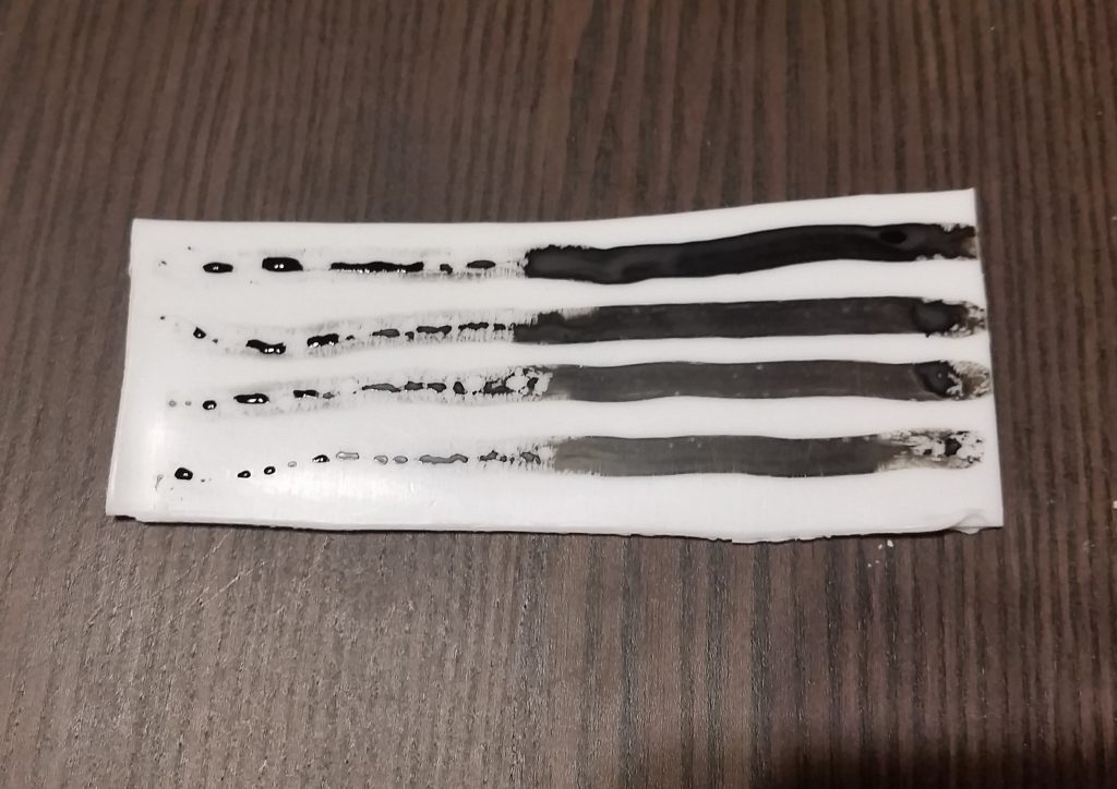
DEMONSTRATION 2: PRACTICAL SURFACE TREATMENT
This next video demonstration exemplifies a practical application of gliding arc discharge plasma technology for surface treatment of hydrophobic surfaces to enhance wettability. In the video, a sample of non-stick parchment paper is treated to allow for significantly better adhesion of an ink, using the ink streak test. The ink streak test is a very common method of surface activation testing in materials science, where a liquid is slowly drawn across the surface of the test sample. Surfaces with very low surface energy (un-activated, hydrophobic surfaces) will cause the liquid to bead up on the surface. However, an activated surface with high surface energy will spread the liquid evenly across the surface. For quantitative testing of surface activation, you can actually buy calibrated liquid kits of liquids at various surface energies to gauge to level of surface activation. However, using a similar high-power plasma treater like the one presented will easily activate even difficult surfaces such as Teflon with a few minutes of treatment. In this case, most liquids, such as plain water, or inks, will provide more than enough information whether or not the surface has been successfully activated. A cotton cue tip is used to draw the ink across the surface. The plasma treater was run in high power mode (>1kW) using the dual MOT supply.
For comparison, an additional test was run after to check the activation ability of this simple DIY setup. The ultimate test is the activation of Teflon. Teflon is widely known for its non-stick surface, making it very difficult to coat and glue. This is largely in part due to Teflon’s extremely low surface energy – at only 19 dynes/cm, it is one of the lowest surface energy plastics available. However, with a few minutes of treatment with the gliding arc system, the surface was well activated, allowing for the deposition of a uniform layer of ink on the surface without beading. In the picture below, the left side of the Teflon is untreated, while the right side was treated.
One thing to note is that while the surface has been successfully activated, allowing for coating of the ink on the surface, this doesn’t make the coating permanent. It can still be rubbed off in this case – wettability and adhesion is greatly improved, but does not mean that treatment will immediately make any applied dye or glue permanent, just that it will adhere better than in its un-activated state.
Another interesting thing to note is that activation of the surface is also not permanent – the surface will eventually fall back to its low-energy state over time. However, depending on treatment and post-treatment handling, this activation time can last up to weeks or even months. In my experience, the surface was re-tested even several days after initial treatment without loss in activation via ink-streak and water drop tests.
GOING FURTHER
Now that a high power gliding arc surface treatment system has been explored and demonstrated on an extremely low budget and with minimal parts and tools, a wide range of experiments can now be performed. The electrodes themselves can be redesigned for smoother, more laminar flow of the arc and for wider surfaces. Power can be increased for faster treatment times. Various process gases can be tested and compared. One unique advantage to this treatment is that it is highly directional on the surface – meaning that only surfaces directly exposed to the plasma are activated, allowing for the use of masking to create various different zones of activated and un-activated surfaces. This can have many exciting applications in areas such as paper microfluidics. In addition, other experiments such as food sterilization can be explored, as well as looking at the effects of cell damage under a microscope.
To treat even larger surfaces, arrays of treatment electrodes can easily be constructed. This type of system is also highly ideal for adapting to CNC technology, and by attaching the plasma treatment head to a multi-axis system, both large-scale 2D sheets and 3D surfaces can be treated. The plasma head can be placed on a simple XY system and scanned over large surfaces. These systems are also well suited for conveyor based processing, where the head, or an array of heads are stationary over a moving conveyor system, for treating rolls of paper/fabric prior to printing or dying, or treating various plastic objects in an assembly line prior to printing.
Another potentially exciting use for this technology is in advanced 3D printing. I have run tests using this system to activate the beds of 3D printers, and printing directly on the activated surface. Just like the water drop and ink streak tests, the molten plastic layers also exhibit surface spreading. This could potentially be used to further explore improved layer-to-layer adhesion with a plasma treatment head integrated with the 3D printer.