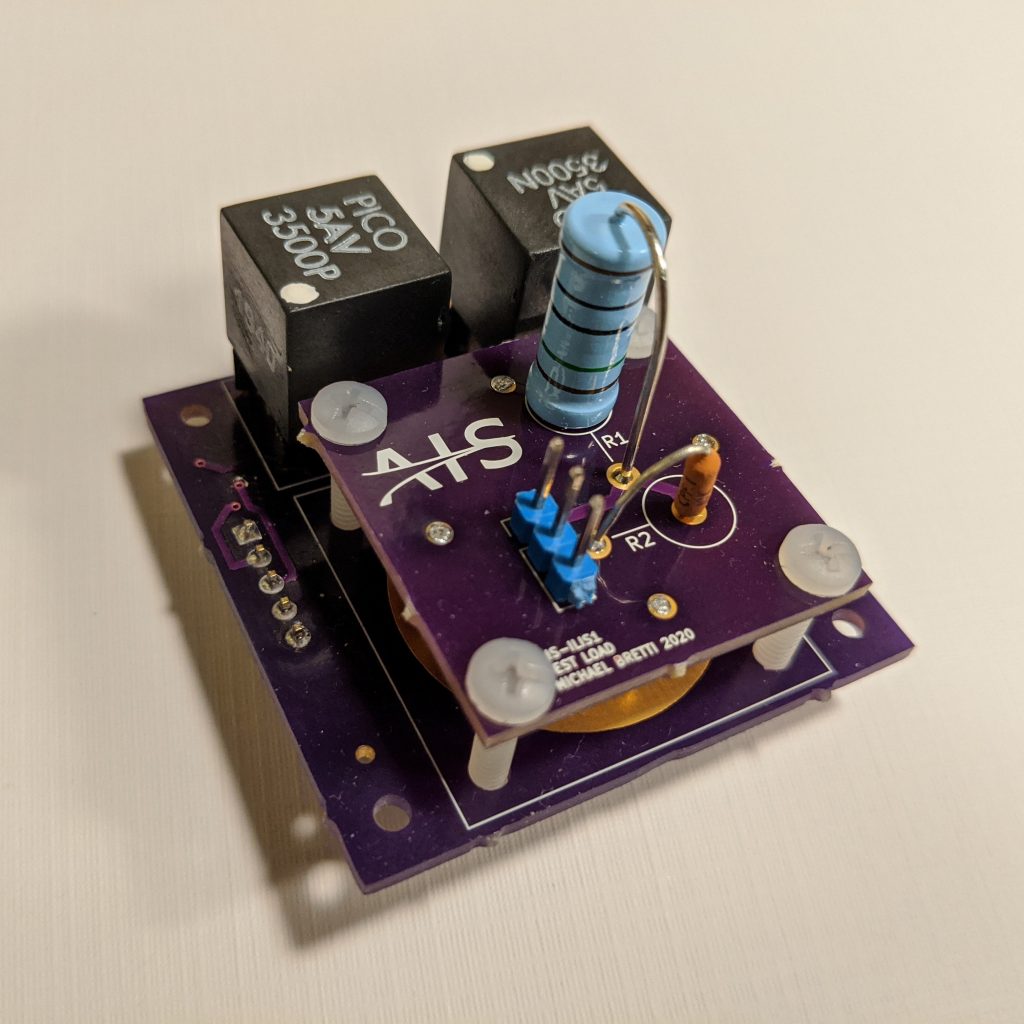
If you have been following my efforts on Twitter, you will have seen that there have been delays with qualification testing of the AIS-ILIS1 V1 electronics. UPS appeared to have misplaced the package, and I have been actively working with them and Pico Electronics on a resolution.
Fortunately, UPS pulled through and found the lost Pico supply. I really wish I had more good news, but unfortunately it ends there. I finally tested the full system over the weekend. Sadly, the ILIS1 V1 thruster electronics does not work.

Individually, each supply performs perfect. Mounted on the board together however they short though each other. I was told my implementation should not be an issue, but its never been tried before. Each module has a rectifier stack on the output for rectifying the high frequency output of the converter to HVDC. Unfortunately the rectifiers just allow the opposite polarity to pass through, as opposed to appearing as a high impedance in the circuit, since the outputs of both modules are tied together to the emitter connection, and alternated on back and forth during operation.
To date this is the biggest disappointment and failure yet for my efforts. I say this each new test that goes by, but as the stakes get raised higher each time, more is on the line. This however is a substantial setback for something so crucial. I will have to think how to proceed moving forward. For larger Cubesat systems that can afford an extra watt or two and plenty of space for HV switching this is not a major issue, but scaling down to the PQ level still remains a wall I have not yet managed to scale. However, talking with some other makers in the community, I have been given a lot of excellent suggestions, and one in particular by Niklas Fauth (@FauthNiklas), appears to be the solution to this conundrum that just might save this effort yet. Big shout out to Niklas for your awesome suggestion!
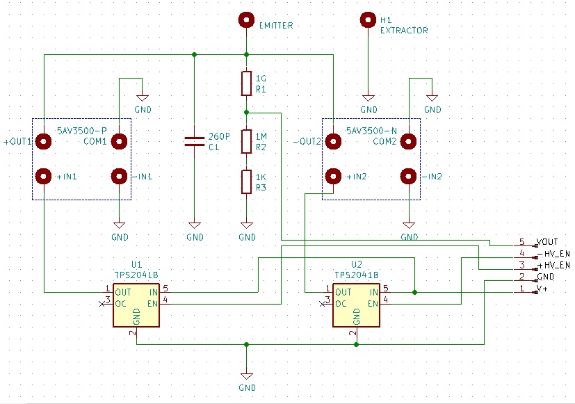
Below is the schematic for the AIS-ILIS1 V1 board. The design is now officially obsolete since it failed qualification testing, however I am making it available for reference and documentation purposes. The V2 design is already in the works, and am looking to hopefully start prototyping soon! Both the high voltage and low voltage sides will be reworked, and hopefully I will be able to verify the new prototype design in the next week or two, and get the new boards made before the end of April. This unfortunately pushes testing back to at least May now, however I am glad there are still options to move forward with on this challenging effort. Absolute worst case scenario, I can still attempt to fire the thruster in vacuum in unipolar mode for a few minutes to try and demonstrate ion emission.

The support and encouragement of the community has been tremendous as always, and always helps continue to push me along and motivate me despite setbacks. A big thanks to everyone out there who continues to follow and support my efforts! It’s a long a challenging journey, with more failures than successes, but we are pulling through this together to change the landscape of electric propulsion!
