UPDATE LOG
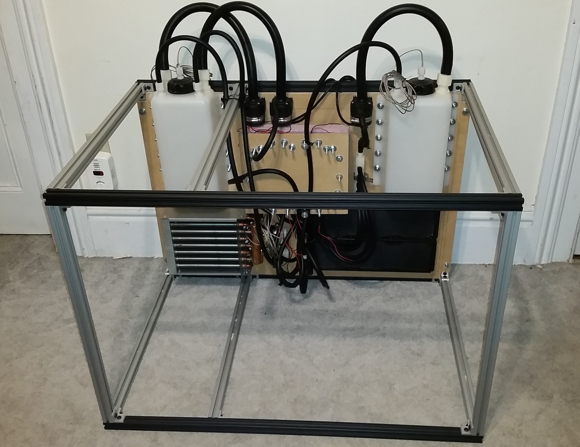
- 08/08/2018 – Main systems of the cooling system completed and mounted to 80/20 test stand.
- 08/14/2018 – Build details officially completed and released.
- 08/20/2018 – Initial testing of the cooling system started.
- 08/21/2018 – During preliminary testing and qualification of the closed-loop diffusion pump cooling system, it was discovered that the water-cooled baffle is made from steel instead of stainless steel, causing severe rusting. As a result, this component will no longer be used for any of the high vacuum systems in development. A new system topology is under development with a larger stainless steel 8″ baffle and modular adapter plates.
- 08/23/2018 – As of recent preliminary testing and qualification on the system, the initially described system topology did not meet spec, and as a result has undergone several minor modifications to correct for this. This was primarily attributed to the cooling fans for the heat exchangers. Both fans were found to not provide enough airflow to achieve the specified thermal dissipation for the heat exchangers, and as a result, both the cold side and hot side loop performance suffered. In addition to changing the fans for increased cooling capacity, several other key changes were implemented to update the system: Details of the new V2.1 modifications are reflected below. A summary of changes is as follows:
- Fan banks consisting of multiple high flow computer fans added to the primary and secondary heat exchangers, replacing the original 12V performance car radiator fans
- Additional fans added around the system to promote further heat dissipation
- Foam thermal insulation added to the cold-side lines to prevent condensation and increase thermal efficiency
- Foam insulation added to the primary tank to increase thermal efficiency
- Two additional flow sensors were added – one for the secondary loop, and one for the tertiary loop, for both system feedback monitoring and interlocking
- PWM control of all three pumps is implemented for better control and optimization of the system during operation
- 02/13/2019 – New cooling fans added to cooling system.
- 02/21/2019 – Cooling system wiring completed, routed, and tested.
- 02/22/2019 – High vacuum pumping stack mounted to Integrated Test Stand and final cooling lines run.
- 02/27/2019 – Slight leak in TC3 repaired. Final cooling system leak test check run.
- 09/02/2019 – Cooling system is no longer active, and is currently obsolete. A new system is in the process of design to replace the current cooling solution.
OVERVIEW
This closed-loop peltier water chiller for diffusion pump cooling serves as an integral subsystem for several high vacuum test chambers. Several major high vacuum systems that are under development all require the use of water cooled diffusion pumps. In order to save cost, a single, integrated, and tightly controlled closed-loop water chiller was designed to handle a wide range of heat loads that would be encountered during normal operation of the selected diffusion pumps. For water cooled diffusion pumps, water cooling is essential for proper and optimal performance, and to prevent overheating and damage to the body, heating element, and burning of the oil used to pull a vacuum in the system.
At present, two diffusion pumps will be used for a wide variety of high vacuum system experiments: an Edwards EO4 diffusion pump, and a NRC 0183 (Varian VHS-4 equivalent) diffusion pump. The primary pump employed for the majority of high vacuum systems will be the Edwards EO4, which operates at 850W. The NRC 0183 is a larger pump that operates at 1450W. Both pumps require water cooling temperature at the outlet between 15C and 25C. Thermal simulations have been completed to estimate the steady state response and operating temperatures of the Edwards EO4 and attached water cooled baffle and adapter plates when the diffusion pump temperature is held at 20C.
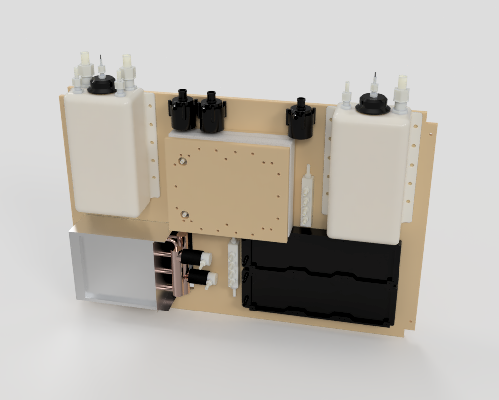
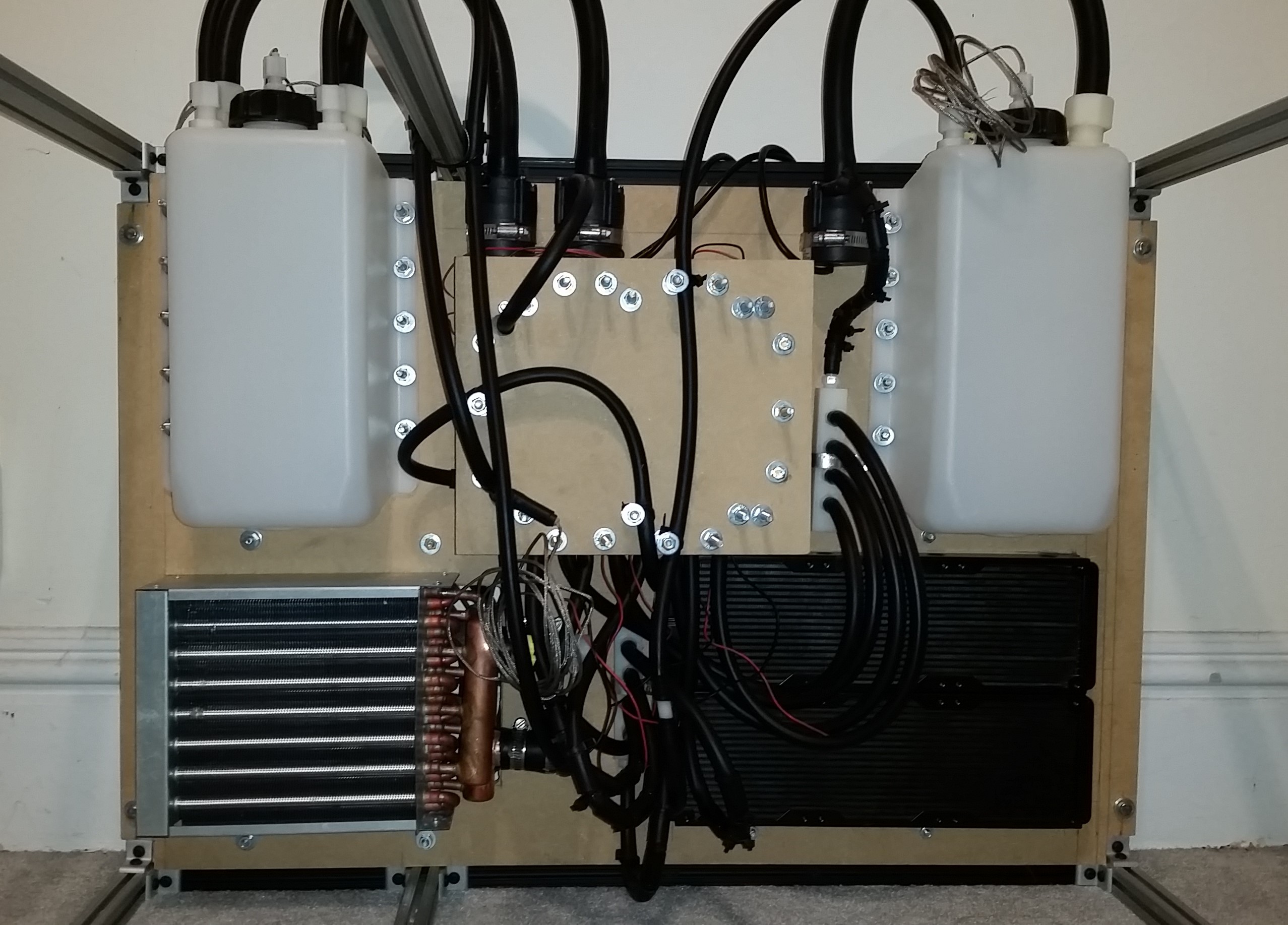
The closed loop water chiller features a triple-loop topology that allows for accurate control and thermal management of the system. The present iteration is rated for a maximum heat load handling capacity of less than 1kW. An additional 300W-400W of cooling capacity is employed utilizing a water-cooled peltier chiller block, making up the second loop of the system. This loop runs in parallel with the primary loop, with coolant constantly circulated between the chiller block and the main storage tank. This is to allow for controlled cooling of the water, and to bring the temperature of the system below ambient to a desired operating level. The chiller consists of eight TEC1-12708 peltier coolers on a custom built cooling block made from high-quality recycled copper heat sinks from servers, with aluminum block water cooled heat exchangers used for cooling of the hot-side. All cooling lines as well as the cold side of the peltier chiller block are thermally insulated to minimize heat losses to the environment.
The third loop of the cooling system is used for liquid cooling of the hot side of the peltier chiller block. Three solid copper heat-sinks with integral cooling fans are mounted directly to the hot-side aluminum liquid heat exchanger to provide initial heat extraction. Two additional 500W aluminum heat air-to-liquid heat exchangers, for a total heat-load capacity of 1kW, are used to extract the remainder of the heat before the cooling water enters the secondary storage tank. Coolant is pumped in the tertiary loop pump from the secondary storage tank, where it is run to peltier hot-side cooling blocks in parallel, followed by the heat exchangers in parallel, directed through a very low cost, custom made nylon block manifold. This loop is isolated from the primary and secondary loop, and uses only aluminum components to eliminate galvanic corrosion from the copper and stainless steel components used in the primary and secondary loops.
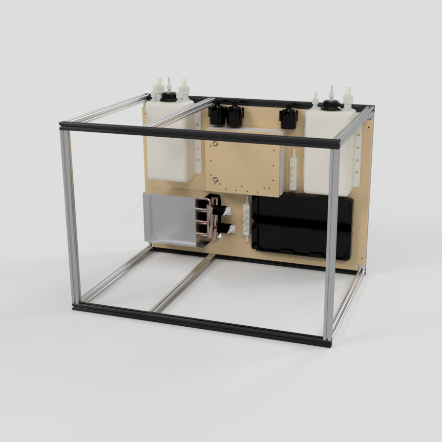
The coolant selected for the cooling system is a mixture of distilled water and inhibited propylene glycol. Coolant is circulated from the tank through the diffusion pump, where upon exiting the diffusion pump enters the primary heat exchanger, and re-enters the opposite side of the storage tank. Coolant is simultaneously circulated through the chiller, and mixes with the incoming coolant from the diffusion pump loop at the same end of the tank to ensure more even heat distribution in the tank. The primary and secondary storage tanks consist of 1.25 gallon HDPE rectangular tanks with integral mounting flanges for vertical mounting. All cooling lines consist of EPDM black tubing. Cold lines, specifically coming out of the peltier chiller, and to the primary pump, are insulated with thick insulating foam to help reduce losses. The primary tank is also insulated to help thermal efficiency when the coolant drops below ambient. All connectors and adapters used are made from nylon. The entire system is mounted to a vertical 24″ x 36″ x 0.5″ sheet of MDF, which is bolted to the back plane of the 80/20 experimental test stand.
For feedback and monitoring, the system employs six modified K-type thermocouples with 1″ 316 stainless steel housing epoxied on the thermocouple wire junction, mounted along various parts of the system with custom-made nylon adapters: one at the water cooled baffle inlet, one at the diffusion pump inlet, one at the diffusion pump outlet, one on the main water tank, one on the secondary water tank, and one on the output of the peltier chiller module. In addition to water temperature feedback, ambient temperature and humidity with a digital dual sensor is used. Water flow rate through all three loops is also monitored to ensure coolant is always flowing, for both system monitoring and safety interlocking. Diffusion pump power is interlocked to coolant flow and temperature, in addition to inlet vacuum pressure. Motors are controlled via PWM to set optimal speeds, and peltier, fans, and diffusion pump power controlled by a 16-channel relay board. The entire system is monitored and controlled by an Arduino Mega micro-controller.
TECHNICAL SPECIFICATIONS
- Type of System: Closed Loop
- Number of Cooling Loops: 3
- Coolant: Distilled Water w/ Inhibited Propelyne Glycol
- Primary Loop Heat Load Capacity: <1kW
- Secondary Loop Heat Load Capacity: 300W-400W
- Tertiary Loop Heat Load Capacity: <1kW
- Estimated Nominal Power Consumption: 800W
- Sub-Ambient Chiller Element: x8 TEC1-12708 Peltier Thermoelectric Cells
- Main Water Tank Capacity: 1.25 Gallons
- Secondary Water Tank Capacity: 1.25 Gallons
- Primary Heat Exchanger: 8″x9″ Solid Copper Tubing Furnace Heat Exchanger w/ Aluminum Cooling Fins
- Secondary Heat Exchanger: x2 500W Aluminum Air-to-Water Heat Exchangers
- Number of Water Pumps: 3
- Water Pump Flow Rate: Up to 5 GPM
- Water Pump Max Pressure: Up to 58 PSI
- Water Pump Max Head: 25 ft
- Number of Cooling Fans: 21
- Thermal Monitoring: x6 Modified K-Type Thermocouples
- Thermocouple Amplifiers: AD595 Thermocouple Amplifier
- Water Flow Monitoring: x3 YF-S201 1-30GPM Flow Sensor
- Ambient Temperature and Humidity Sensor: DHT22 Digital Temperature/Humidity Sensor
- System Control: Arduino Mega
- Thermal Compound for Heat Sink Bonding: Arctic Silver 5
- Cooling Lines: Opaque Black EPDM
- Cooling Line Connectors/Adapters: Nylon Jaco Bulkhead Compression Fittings, Nylon NPT to Hose Adapters
- Cold Line Thermal Insulation: R-3.2 Foam Pipe Insulation
CAD FILES (.STEP FORMAT)
COST ANALYSIS
-
Total Cooling System Expenditures.PDF
-
Closed-Loop Peltier Water Chiller for Diffusion Pump Cooling Expenditures Report.PDF
-
Peltier Chiller Module Final Expenditures Report.PDF
-
Thermocouple Build Final Expenditures Report.PDF