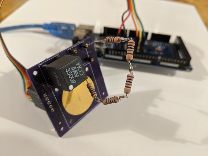
With the new AIS-ILIS1 V1 board soldered up, testing has officially begun on the ILIS1 thruster electronics. While I am still waiting on the -HV supply, there is plenty of work qualifying the +HV supply and general timing in the meantime. The Pico Electronics supplies selected for this thruster seem just as robust as their EMCO counterparts used on my prior AIS-gPPT3-1C pulsed plasma thruster, handling direct arcing short circuit loads without issue.
From my previous builds, one big lesson I learned is to not solder the expensive HV supplies directly to the board, especially since there will be changes and new iterations! So I am now using sockets for the supplies on all prototypes going forward, making this way easier. A simple Arduino script is being used to run the thruster sequence, allowing me to adjust the on/off cycle for each supply as well as the transition delay. Getting this timing optimized will be crucial for maximizing thruster performance with my major space and power constraints.
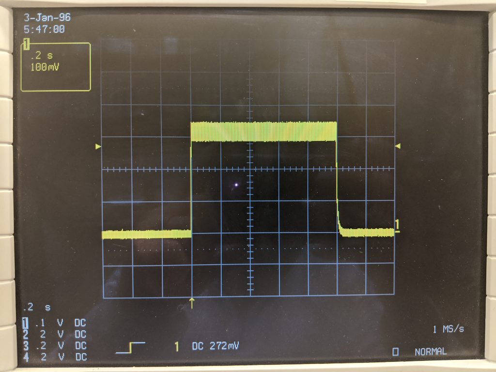
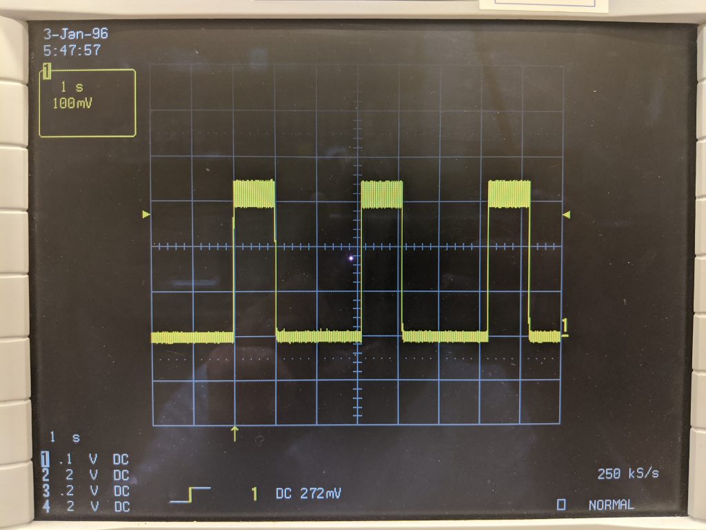
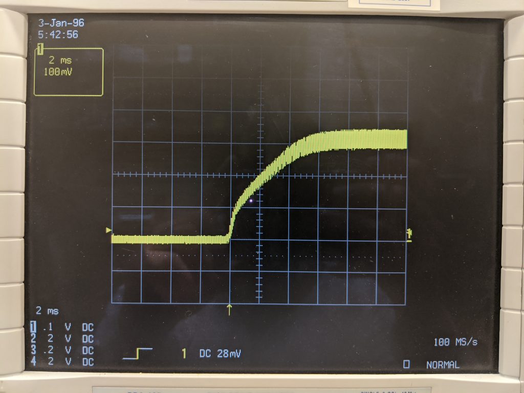
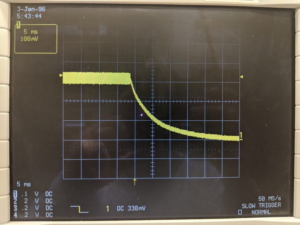
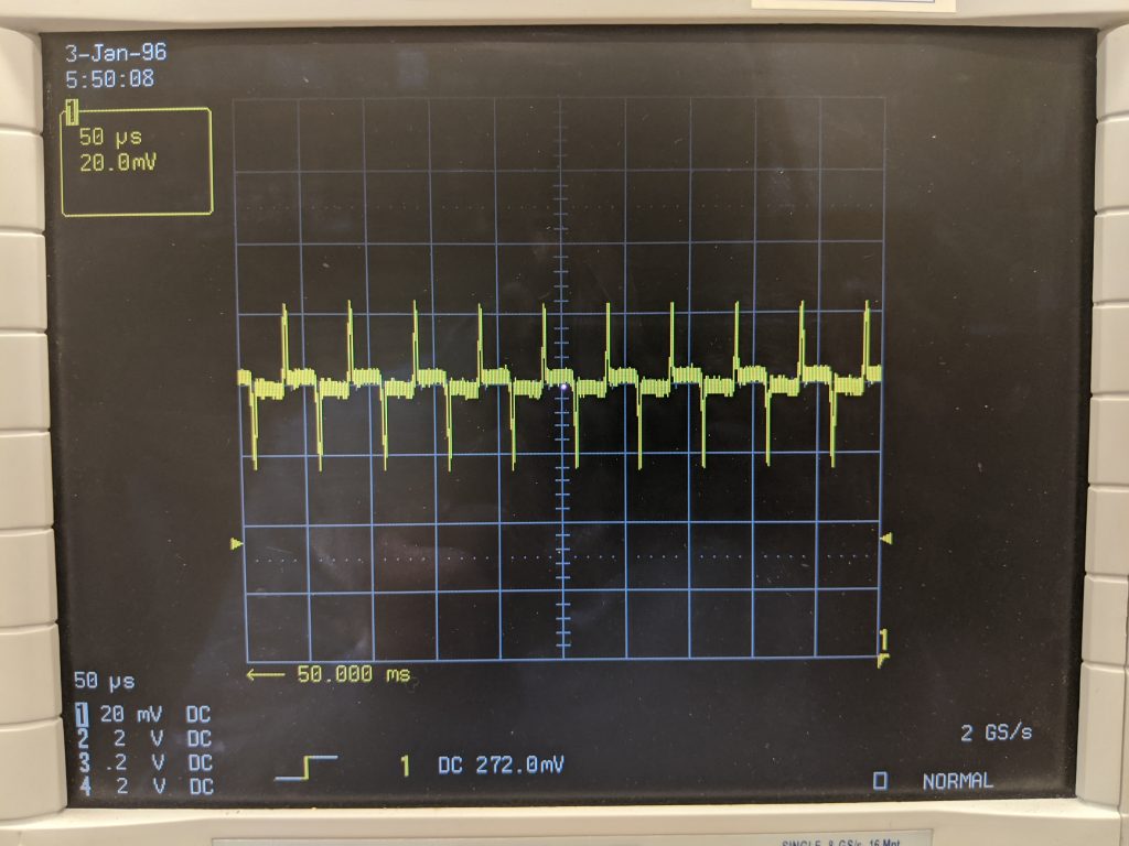
The first measurements of the AIS-ILIS1 electrospray thruster board were completed on the +HV supply looking at the pulse, rise, fall, and ripple under full load and reduced output filtering. The next testing will be with both supplies and full timing sequences. Scope traces can be seen below on the various pulse parameters, at 100mV/kV division. The pulse train of the thruster sequence was controlled with the +HV supply active by an Arduino. 1Hz nominal operation, with slight delay between +HV and -HV turn-on. Once the -HV supply is in, and the thruster is operating in vacuum, timing will be optimized based on emission response.
A big unknown until actual ignition testing is the load characteristics. The emitter acts as a nonlinear load – it is an diode ion gun, responding exactly like a diode in its VI characteristic curve for emission, making simulating an exact load on the bench difficult. For now, I am using a simple resistive load of different values in the M-ohm range for qualifying the HV supply drive response under different loading conditions, which is usually more than accurate enough for basic bench testing and qualification of pulsed diode gun loads. I will look into building a load on a PCB that interfaces with the board so measurements can be made when both supplies are running. The key parameter will be to see how residual charge on the shared output cap effects driving the load when reversing voltage.