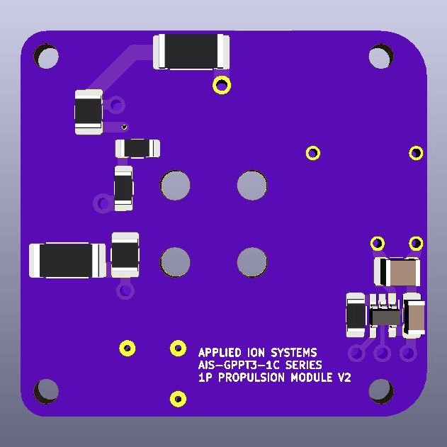
Quick update on the propulsion front for the AIS-gPPT3-1C series propulsion module. In my previous posts, I have reviewed the final V1 board design, new boards, and initial atmospheric testing results. As I talked with other PQ developers potentially interested in propulsion, I have gained new insights and ideas to make the module more directly compatible. As a result, I have already completed the final design for the V2 board revision. New features include direct voltage monitoring of the main bank and ignition bank, as well as direct triggering from a standard 3.3V logic pulse down to the required 1V for the thyristor.
The first changes, as mentioned above, allow for the user to directly read high voltages in key points on the board directly to whatever microcontroller is being used. Using very high value (giga-ohm), high voltage pulse-rated SMT resistors as a simple voltage reading divider, the 1300V main bank and 300V ignition bank voltages are brought down to 2V for direct analog reading from a PocketQube main controller with analog input capabilities. By verifying both ignition and main voltages drop briefly to 0V after the trigger command, successful firing can be confirmed in space, as well as missed pulse tracking and overall thruster lifetime tracking by counting total number of successful ignitions. In addition, bank voltages can be verified they are at correct operating levels during nominal use, and pulse energies per shot can even be tracked and recorded as well. A simple solution that opens up massive self-diagnostic capabilities with a bit of simple programming!
The next change was in the thyristor trigger interface. The sensitive gate thyristor requires a 1V max logic signal at microamps of current to trigger. However, standard PQ power and logic signals are around the 3.3V level. The current V1 iteration requires a voltage divider or conversion down to 1V from the microcontroller to trigger the thyristor, which makes the current version less directly-compatible. By adding the divider directly on the board to the input of the thyristor gate to bring a 3.3V logic pulse from the PQ controller down to 1V for the thyristor trigger, the module is now fully voltage-compatible with direct connections to the PQ without intermediate circuitry or converters needed. A very simple change, but one that still enhances compatibility. The changes can be seen on the KiCad render below. All of the voltage divider circuitry is located on the back of the board, so the top of the board with all the major high voltage circuitry has remained the same.

The V2 board will be manufactured after full vacuum testing of the current V1 board, in case any additional changes are needed. Hopefully if the V1 board passes with the new thruster, actual flight-ready modules will be available, starting with the new V2 design. And of course these will be in the new OshPark black!
