UPDATE LOG
- 08/30/2018 – Completed soldering of instrumentation and control boards for cooling control and monitoring.
- 09/10/2018 – Mounted control boards to baseplate and started control system wiring.
- 09/15/2018 – Extended trial version of MegunoLink obtained for preliminary control system development and software qualification.
- 09/24/2018 – MegunoLink software license purchased for full development of the control system.
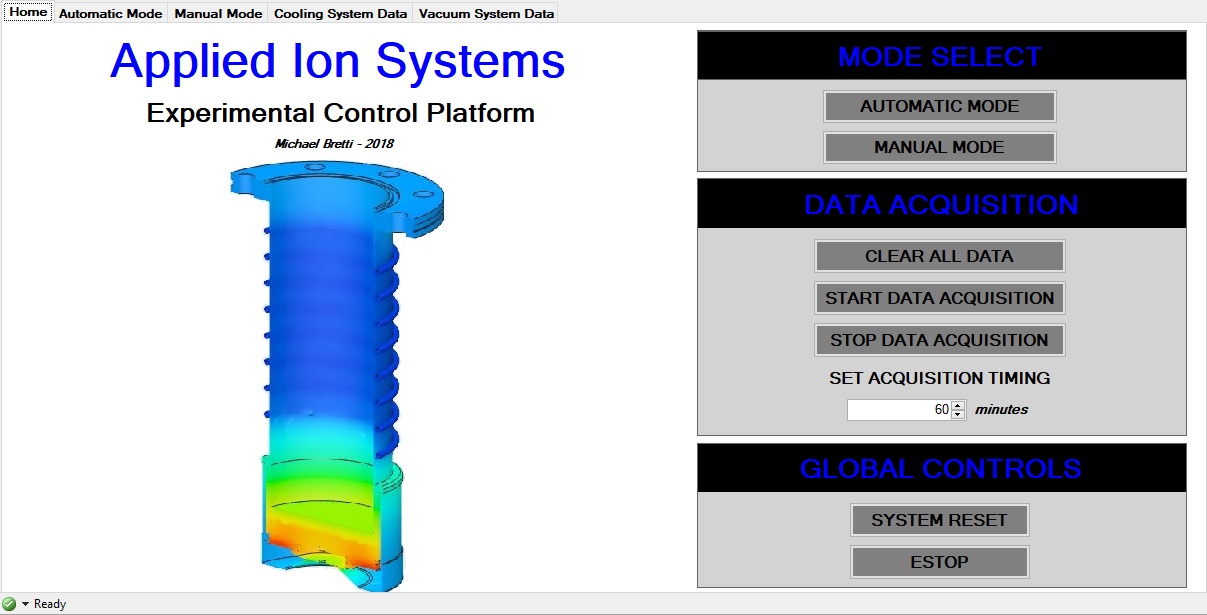
OVERVIEW
For the high vacuum test stands being built at Applied Ion Systems, monitoring, data logging, remote and local control, as well as interlocking are critical for the safe and reliable operation of the experimental systems. A low-cost control system has been designed and built for handling the control and monitoring of these subsystems. The three primary subsystems that are controlled and monitored during standard operation include the closed loop peltier chilled diffusion pump cooling system, the low vacuum subsystem, and the high vacuum subsystem.
The control system is based around the Arduino Mega microcontroller. Various sensor inputs from each of the subsystems are conditioned through the appropriate circuitry, and sent to the microcontroller. Depending on the subsystem and desired parameters, interlocks are established.
For the closed-loop cooling system, a total of ten inputs are presently employed – six k-type thermocouple probes in critical areas throughout the cooling loop, as well as three flow monitors (one for each loop in the cooling system), and a dual ambient temperature/humidity sensor. The thermocouples provide critical performance feedback of the cooling system during operation, and allow the operator to closely monitor thermal conditions of each of the loops to ensure proper cooling and chilling of the critical water-cooled components is being maintained. System performance can be related to ambient conditions if needed, and effects of ambient temperature and humidity on system performance can be observed for reference. Should the temperature in any part of the system exceed a designated operational limit, power to the high vacuum pump will be shut down.
The flow meters are also used for safety interlocking of power to the diffusion pump, in the event of no-flow or low-flow conditions. In addition, the flow meters also provide feedback necessary for controlling the pumping speeds of the three pumps in the cooling system for adjusting flow rates to the required levels, as well as optimizing thermal response of the system.
The cooling system includes numerous outputs, primarily for engaging and interlocking power to critical subsystems. Outputs are controlled through the 16 channel relay board which switches power on and off to the various pumps, chiller modules, fans, vacuum pump power. This allows for both manual control, as well as automated control for automated cooling and vacuum pumpdown sequences.
The low vacuum subsystem input takes data from the thermocouple vacuum gauge located in the roughing line and uses this for controlling power to the diffusion pump for both safety interlocking and automated pumpdown sequences. Once the rough vacuum has achieved the desired level, power to the diffusion pump through the roughing interlock can be enabled.
The high vacuum subsystem input takes data from the HPT-100 wide range pressure transducer located in the high vacuum chamber and uses this for critical interlocking of power to the high vacuum diffusion pump, as well as general process monitoring. Should the vacuum level exceed a critical point where operation of the diffusion pump becomes unsafe, power is disconnected from the diffusion pump through the relay board.
In addition to the physical control system sensors, circuitry, and microcontroller, a user interface has been developed for remote access, control, and monitoring in real time of the various subsystems. An interface using MegunoLink has been implemented to allow for bidirectional communication between the control system and the user interface. The program allows for easy and rapid development of an advanced user interface, displaying sensor data, data acquisition graphing, system controls, interlocks, and alarms.