INTRODUCTION
As part of the design and build of the Integrated High Vacuum Test Stand, several custom adapter plates needed to be designed and manufactured to mate the high vacuum diffusion pump and baffle to the chamber. Unfortunately, all of the components are not the same standard, necessitating the requirement of custom plates. The plates have already been designed and integrated into the final cad for a while now, and can be viewed in the Integrated High Vacuum Test Stand Gallery. This post will briefly cover some of the design challenges and considerations faced for the adapter plate, and some of the solutions that were implemented as a result.
OVERVIEW
The current system design calls for two adapter plates. The first plate sits above the diffusion pump, with blind tapped holes on the bottom to allow the pump to be bolted directly to the plate. This creates the first interface seal between the pump and plate via an o-ring located in a groove on the flange of the diffusion pump. On the other side of the plate is an o-ring groove that allows for sealing between the plate surface and the large 8″ baffle that is used to minimize oil backstreaming from the pump. In addition, the adapter plate includes mounting holes at the edges to bolt the entire assembly to the 8020 test stand. The CAD design of the plate can be seen here (top side of the plate):
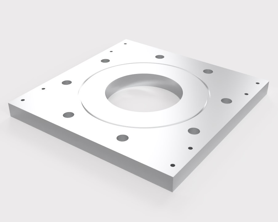
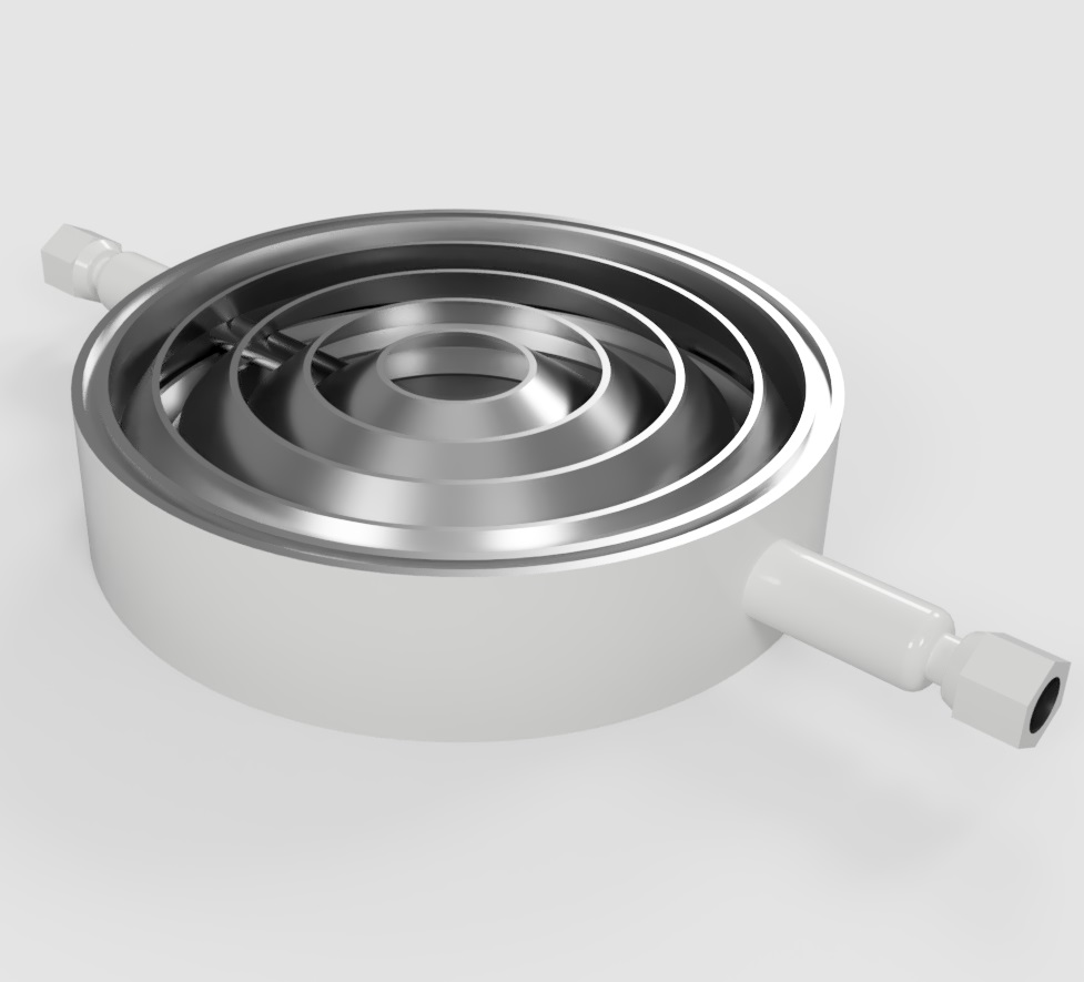
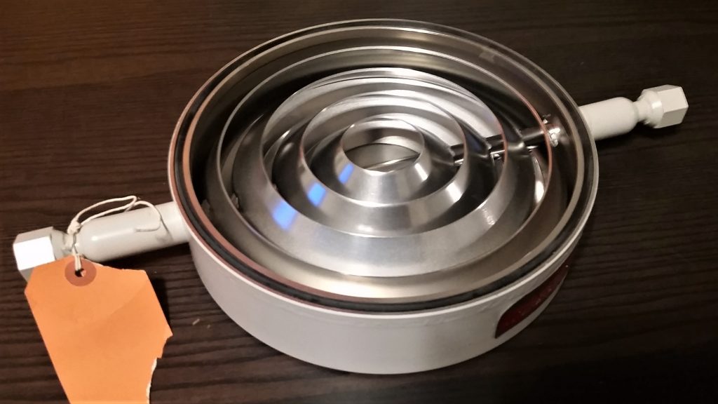
The baffle sits directly above this, with the flat edge of the baffle on the o-ring in the plate groove. The top of the baffle also has its own o-ring groove, which mates with the flat bottom surface of the second plate. CAD and a picture of the baffle can be seen as follows:
Finally, the second adapter plate sits on top of the baffle, and adapts the entire pumping assembly to the conflat chamber. For the various high vacuum systems currently under development, each system has been designed around 6″ conflat hardware to allow the pumping stand to accommodate any of the various chambers, and rapidly change between experiments as needed. As a result, a mating surface for 6″ conflat hardware needed to be designed for the top plate. Blind tapped holes needed to be used for mounting the conflat flange to. Large through-holes for 5/8″ bolts are located in each plate to clamp the entire assembly together and create seals between the o-rings on both the adapter plates and baffle, sandwiching the baffle and securing it into place. The second plate design can be seen below:

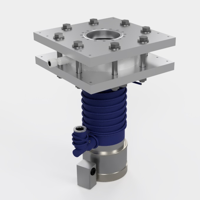
Finally, the full assembly for the high vacuum system is as follows:
Due to severe cost constraints and budget, the plates needed to be designed with as minimum manufacturing as possible, out of an affordable material. While stainless steel is the ideal choice, for the size of the plate required to accommodate the flanges and mounting holes to the 8020 test stand (12″x12″x1″), this would have been far too costly. Aluminum was selected for the material as a result of its low cost. For o-ring seals for vacuum applications, the recommended surface finish of mating surfaces is 32 micro-inch or better. ATP-5 aluminum plate stock is a type of standard tooling plate that comes with a surface finish of 25 micro-inch or better. While a bit more in cost than regular aluminum plate stock, this eliminates the need for any final surface machining of the plates, reducing overall machining costs. Because I do not have the machining capabilities to do these pates myself, the machining needed to be outsourced to a local machine shop. The plate stock was purchased at a great deal of about $50.00 per plate from Midwest Steel and Aluminum during one of their daily sales.
While a simple o-ring groove for the o-ring sealing surfaces is easy enough to machine, the conflat mating edge on the second plate remained a technical challenge due to the geometry and cost associated with machining the standard knife edge.
ADAPTER SEALING SURFACE DESIGN
A standard sealing method in high vacuum engineering is the conflat flange. This consists of a specially formed knife edge that bites down into a softer gasket material, creating a strong, leak-free seal capable of ultra-high vacuum levels. Generally, due to the large forces exerted on the very small diameter sharp knife edge, the flange must be made of a very hard material, almost always stainless steel. Aluminum knife edges do exist, however they must be hardened, and require more care in machining, and can only use either aluminum or viton seals. As a result, the gasket must be softer material than the knife edge to prevent damage to the edge. The default material is oxygen free copper for stainless steel. Annealed copper gaskets are also available for conflat view ports to reduce potential stresses on the glass bonded to the flange. Aluminum gaskets are also available, though less common, as well as viton gaskets. Due to cost constraints and use of aluminum for the adapter plate, hardening through some process (such as nitriding) was not possible, requiring the use of a viton conflat gasket.
Looking at the geometry of the general mating surface interface between the viton gasket seal and the two knife edges, when fully compressed, we can see that the angle of the knife edge compresses down on the same angle in the viton o-ring (for full metal seals, the knife edge actually bites into the copper and deforms the metal.)

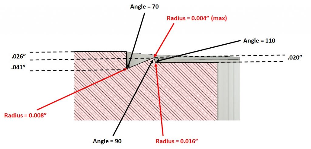
While this presents an ideal sealing surface for high and ultrahigh vacuum applications, it becomes very difficult to fabricate unless you have the setup specifically designed for doing this (like standard vacuum flange manufacturers.) Based on specifications presented in literature the following is standard for conflats knife edges:
– Knife edge diameter should be within 0.004″
– Knife edge radius should not be bigger than 0.008″
– Knife edge eccentricity should be within 0.004″ to the flange middle axis
– gasket recess should be within 0.002″ mm to the middle axis of the flange
– Sealed surfaces must not have any marks/scratches
– Sharp tolerance of sealing surfaces should be within 0.002″
– Knife edge angles should not be smaller than 90 degrees for the ISO/TS 3669-2 standard
Below shows some of the basic dimensions for the conflat knife edge. These can vary slightly between manufacturers:
Quotes from local manufacturer’s for this edge were staggering, on the order of $600 to almost $1k for the plate, making it highly unfeasible on my budget of only a few hundred dollars max for both plates. Therefore, another solution was needed.
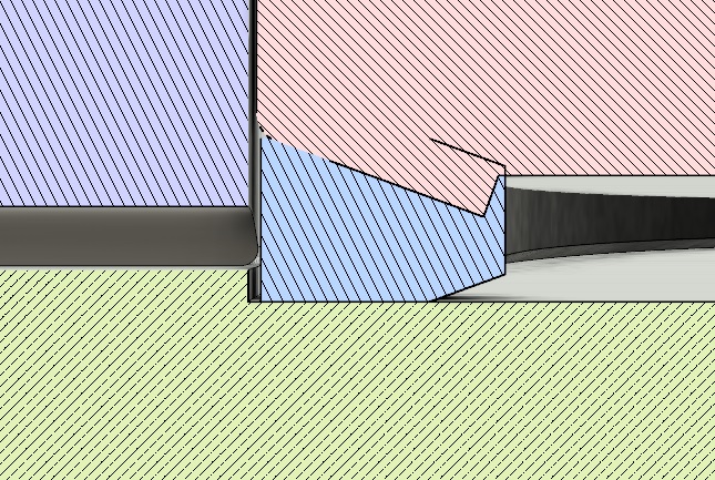
Fortunately, conflat knife edges are not necessary at all for reaching vacuum levels up to 10^-7 torr without too much effort. Viton is commonly used, often seen mainly in KF flanges, or larger ASA/ISO flanges. These seals mate either between flat surfaces with a retainer ring to keep the o-ring centered, or between a flat surface and a groove. There are also, as mentioned before, flat viton seals specifically for conflats, for systems that require rapid assembly or seals that need to be broken often that do not require UHV levels. Since the vacuum systems I am working on do not need to operate above 10^-6, with 10^-7 ultimate pressure, this is well within the range. Since it is also shown that flat sealing surfaces provide valid and widely used options at the high vacuum level, it was decided to use a simple flat sealing surface on the aluminum side, slightly inset about 20 thousandths of an inch to locate the flat o-ring in the proper position during assembly. The depth was also selected to allow for greater compression of the o-ring-ip to almost 50%, where the standard is 30%. While over-compression can permanently deform an o-ring, required a replacement after, it can help reduce permeation to a small extent. In addition it is widely shown that flat cross-section o-rings perform equally, if not better than circular cross section o-rings, eliminating the need for a groove precisely positioning a circular o-ring on the knife edge. The flat o-ring makes it easier to mate directly to the conflat knife edge, and is already provided with standard dimensions for the proper conflat size. The cross-section of the interface can be seen here:
THE NEXT STEPS
With the design and analysis of the plates completed, and the plates already fabricating having written this entry, the next steps will be the assembly and preliminary vacuum testing of the high vacuum assembly. New technical challenges have presented themselves along the way, and while creating more setbacks and difficulties, has allowed for new learning opportunities. The next blog post will take a look at the newly machined plates, and the beginning stages of assembly and testing of the hardware.