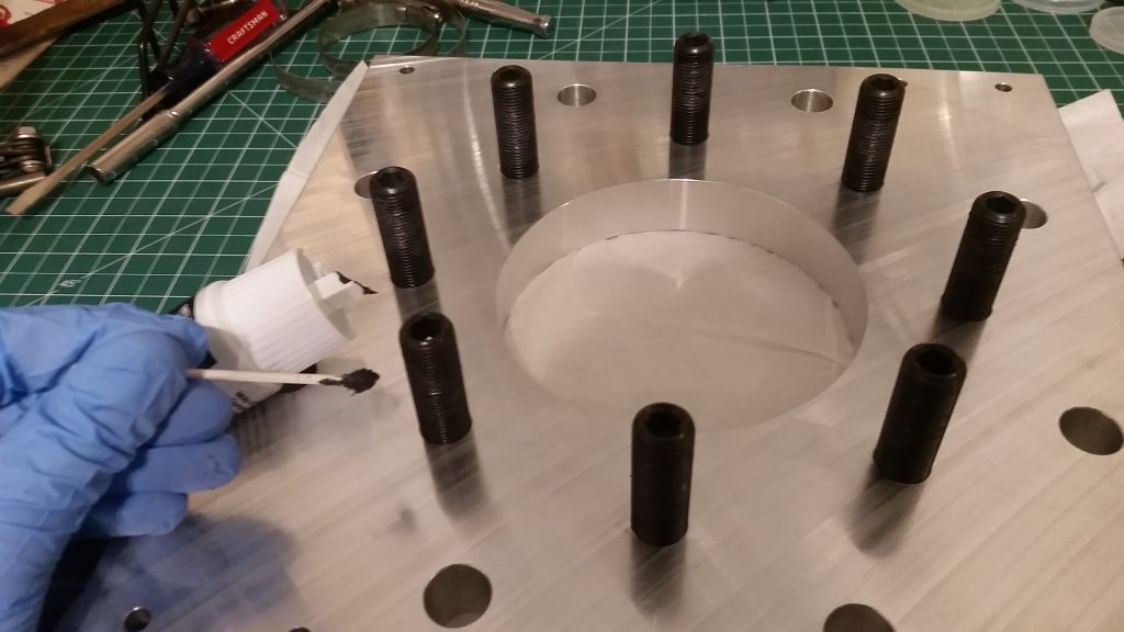
In the previous blog post, I covered some of the modifications needed for the newly manufactured vacuum adapter plates, which primarily consisted of using Loctite to secure alloy steel set screw studs into the blind tapped holes on the plates to minimize the potential of thread stripping during assembly and disassembly, particularly when switching vacuum chambers. With the plate modifications completed, the entire vacuum pumping assembly can finally be assembled and tested.
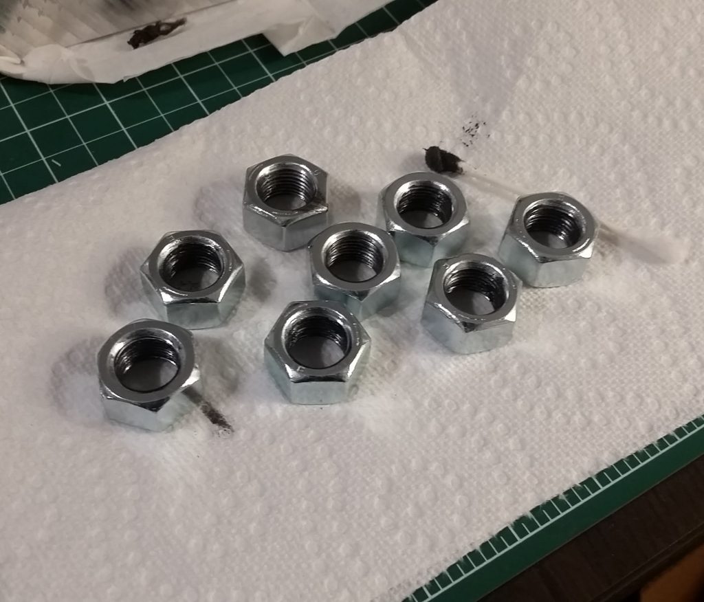
The first stage of preliminary assembly preparation was applying anti-seize to the steel studs and nuts for the first adapter plate, which attaches directly to the diffusion pump. I went over several different options, and decided to settle on a non-metal based antiseize Moly-Lit, which consists of Molybdenum disulfide and graphite. The antiseize was first applied to the studs as well as the threads of the nuts. Absolute care is needed to prevent the antiseize from getting on any part that will be exposed to vacuum.
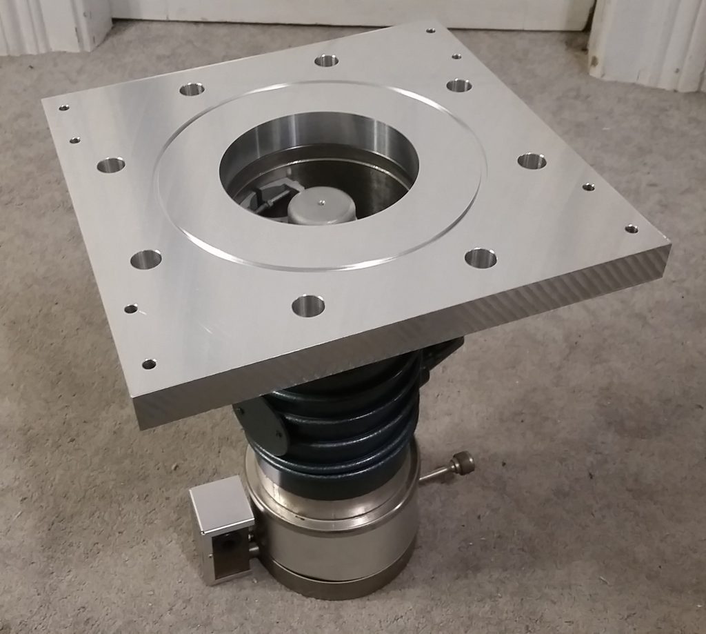
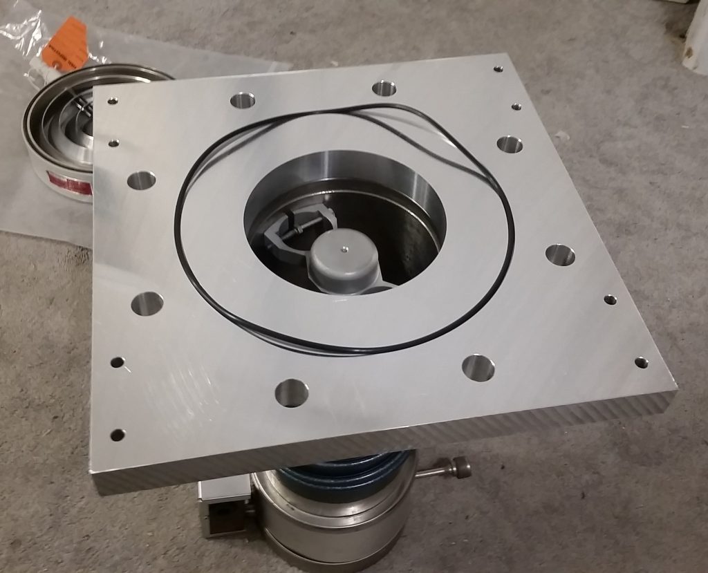
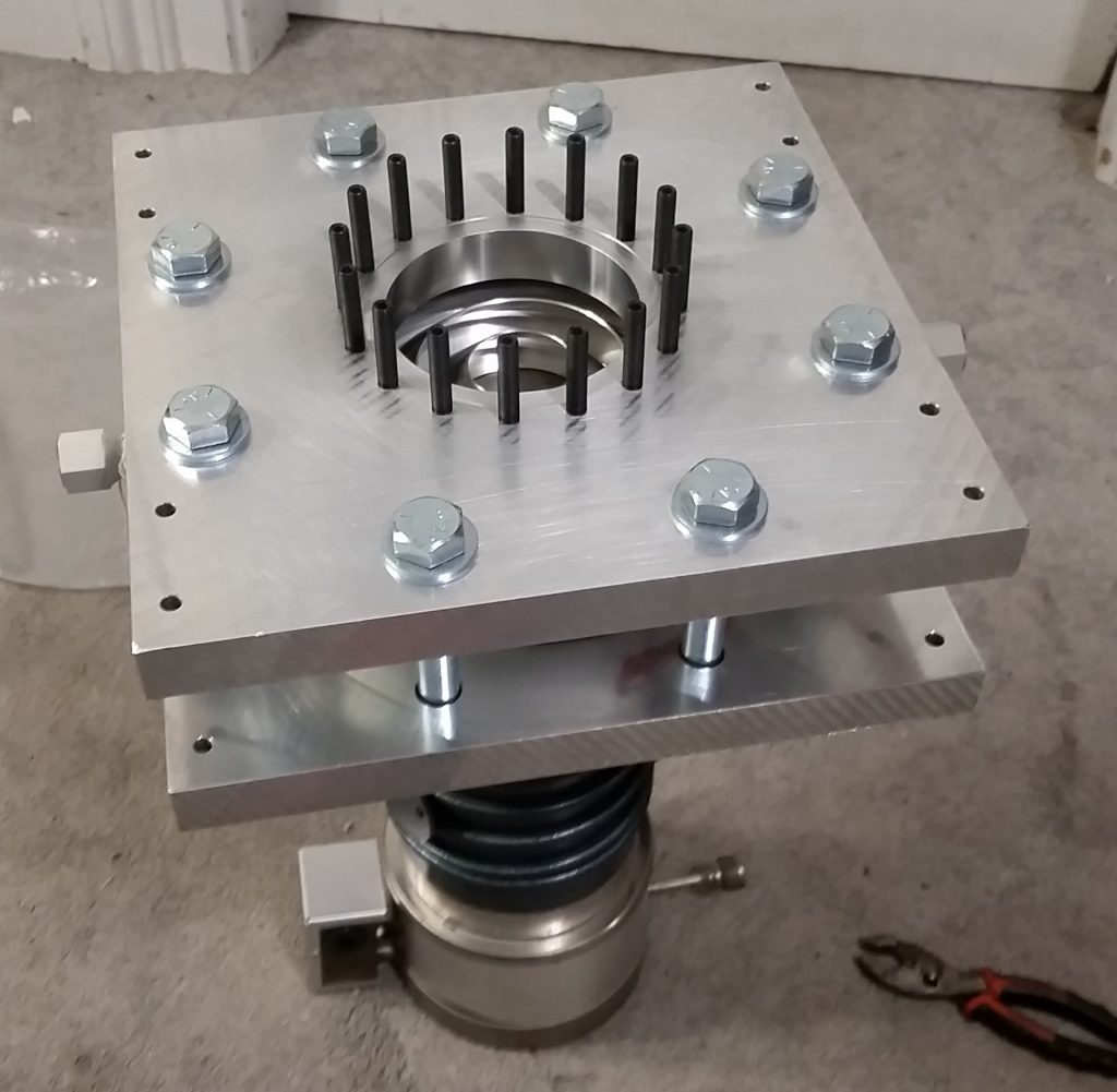
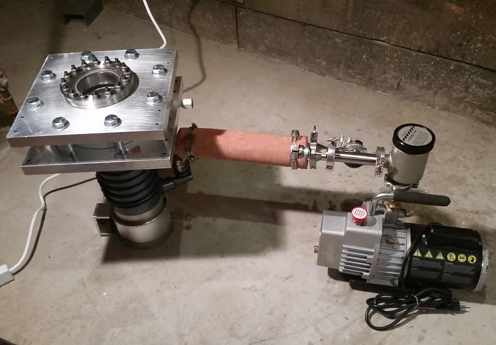
Once complete, the plate was carefully aligned and placed into position on the diffusion pump, and the nuts were tightened down to secure it in place. Next, the o-ring was inserted into the groove, followed by the high vacuum baffle. With the baffle centered on the assembly, the top plate was then placed onto the baffle. The clamping holes between the two plates were carefully aligned, where eight 5/8-13 bolts 5″ in length are used to compress the o-rings on either side of the baffle surfaces between the plates. The bolts and nuts were also coated with a bit of antiseize as well which greatly helped, a couple of the nut snagged a bit, but with the antiseize they went on smoothly without issue.)

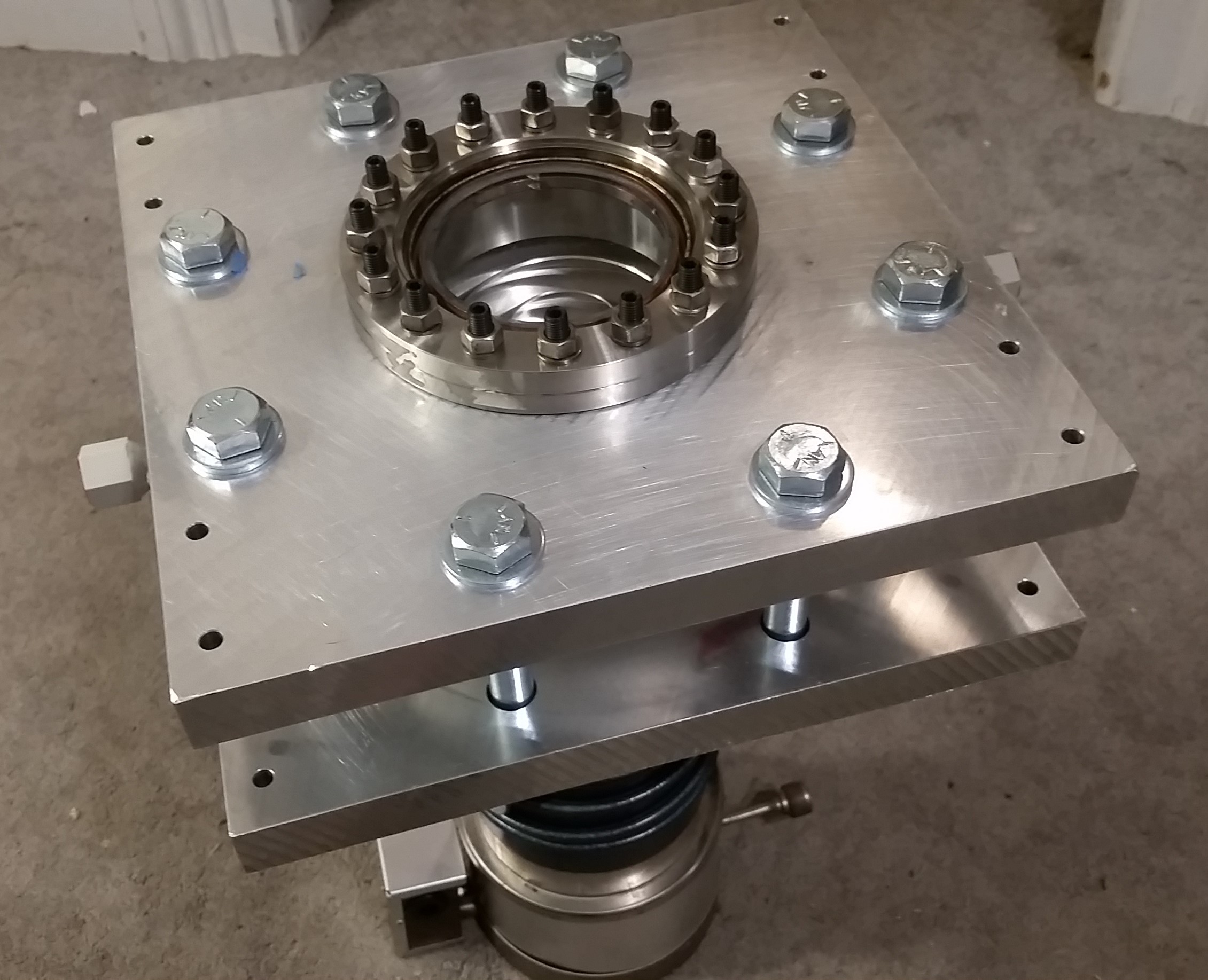
For the first initial leak check test, I would only be using the roughing pump. In order to blank off the assembly, I decided to use the 6″ conflat viewport for the Micro Propulsion Testing Chamber temporarily, with a flat viton conflat gasket. I decided to not use any antiseize for these bolts to keep parts a bit clean since I will be assembly and disassembling it later, and would prefer to keep the antiseize off the viewport.
I discovered that the fit on the bolts was extremely tight – the viewport got on with very careful alignment and a bit of pushing, but it is really close. A bit too close for comfort. Hopefully I can place and remove the chambers as needed without damaging the studs, but it will be tricky. The tolerances on the plate for machining the holes apparently weren’t kept as tight as I had hoped, and the tiny fractions of an inch offset were enough to make this a less-than-perfect fit. It feels like I am always walking the knife-edge between success and failure on this project (vacuum pun intended).
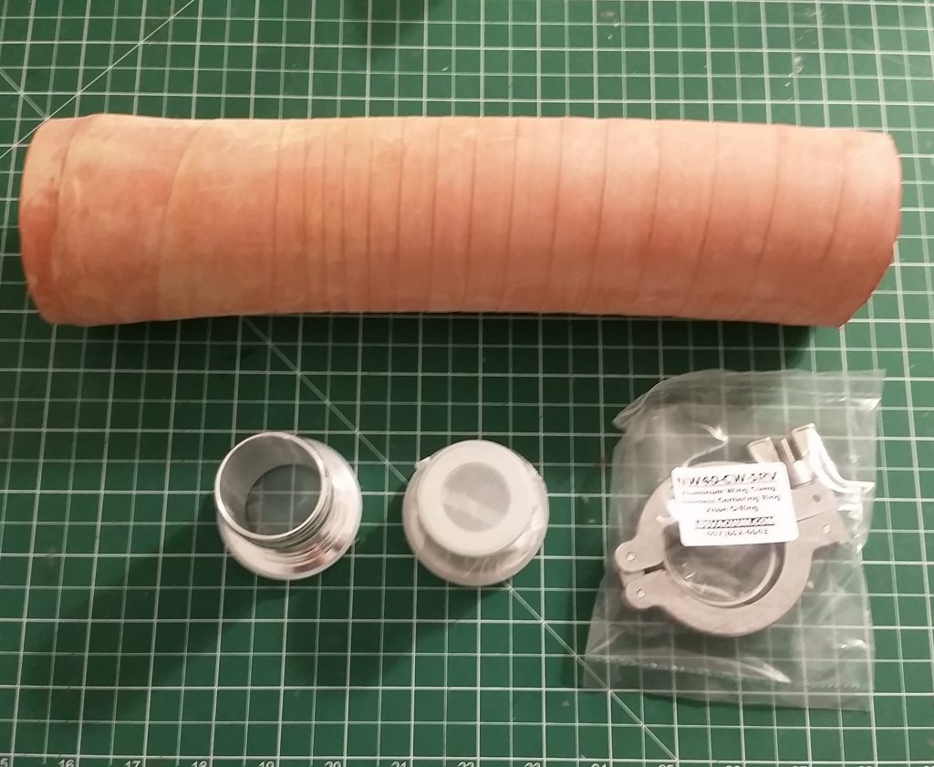
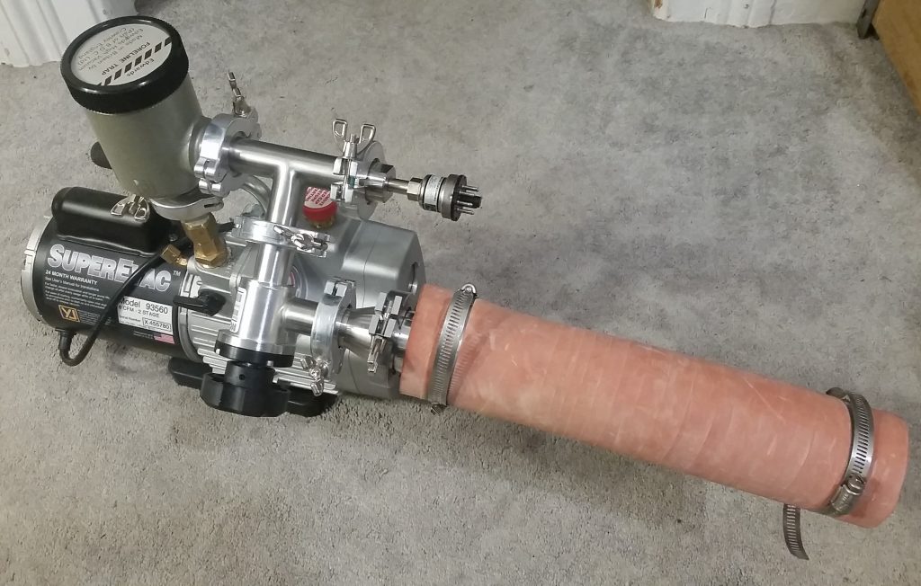
Next, the roughing line had to be disassembled an reconfigured from its initial topology in the original design – I will need to go back and update the CAD files at some point, which are freely available for download. I decided that the best way to connect the kf25 roughing line to the custom Edwards c-clamp roughing inlet was to use a large diameter natural gum rubber vacuum hose. The foreline goes from kf25 to kf40, then a kf40-to-hose adapter. The hose adapter and hose ID is 1.625″. This hose is quite beefy (quite a few jokes on Twitter likening it to a sausage or some Kronenberg-themed vacuum system), and will be cut shorter for the final assembly on the 80/20 table.
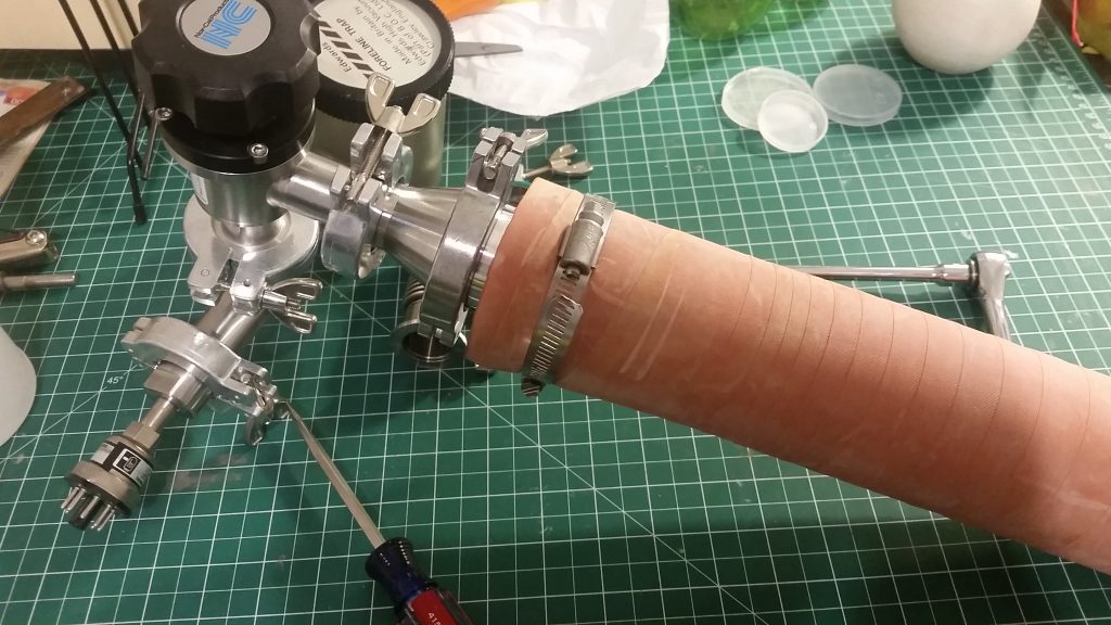
The foreline attaches to the roughing pump via an Edwards FL20K foreline trap, then to a kf25 tee that attaches to a manual isolation valve and the foreline thermocouple gauge. On the other side of the isolation valve, the adapter for the hose is mounted. With the assembly tightened together and mounted to the roughing pump, the roughing system can be tightened to the diffusion pump roughing port, and initial leak checking could begin.
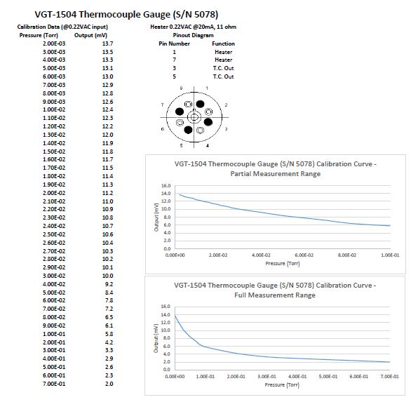
For this test, only the foreline would be used. First, the isolation valve was closed, and the ultimate pressure of the blanked off roughing pump was checked. Back when I did initial calibration and testing of the pump and thermocouple gauge last year, I was able to hit an ultimate pressure of about 12-13 millitorr. After pump down for a while, and re-tightening all of the hardware, I was able to reach the initial calibration pressure of 13 millitorr. Excellent news, meaning that the roughing pump is performing as expected from when first tested! For reference, the initial calibration curve and voltage output values of the gauge is shown below:
Next, the isolation valve was opened, and the entire assembly was pumped down. After a while of pumping, using the gas ballast, and tightening up hardware, I was still having trouble dropping below 70 millitorr. After another hour of pumping, cranking down on the assembly bolts, and re-checking pressure, I was able to settle at an ultimate system pressure of 23 millitorr. While not ideal, considering I have about 10 millitorr left of room that the roughing pump can ultimately reach, it did pass my worst-case limit of 30 millitorr, which signaled that the system is ready for final assembly and preparation for high vacuum testing.
With initial roughing pumpdown test complete, the major tasks now include disassembling the system, cleaning the high vacuum surfaces, cleaning the diffusion pump of 704 oil to prep it for the upgrade to 705 oil, finalizing the reinforcements for the 80/20 table, wiring all of the fans, pumps, and peltier cooling modules on the table for the diffusion pump cooling system, reassembling the pumping stack with 705 oil added to the diffusion pump, mounting the stack to the table, and beginning high vacuum testing. There is a tremendous amount to do, but progress is being rapidly made. The rest of the components are in for assembling the table and the major high vacuum chambers, so I can reasonably expect initial high vacuum testing within the next couple of weeks. This will be a massive milestone for the efforts here at Applied Ion Systems. For one, I will be able to qualify the entire cooling and high vacuum assembly, which has been the main focus of design for the better part of a year. Once high vacuum and cooling passes (worst case 10^-5 torr, ideal case 10^-6), then the true work can finally begin. The two major systems, the Micro Propulsion Testing Chamber for open-source CubeSat propulsion, and EXEDA for open-source high power particle beam systems, can finally come to life, and push forward new areas in the maker community that have yet to be explored before!