After a year’s worth of redesign, waiting, and planning out the system, the adapter plates for the Integrated High Vacuum Test Stand were finally machined and ready to go. These were the last major parts needed for the high vacuum system for assembly and initial pumpdown testing:
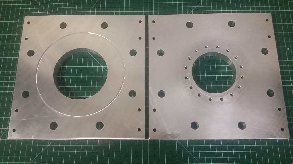
As mentioned in prior posts and on the general project description page, the adapter plates are made from 1″ thick ATP-5 aluminum plate stock. ATP-5 was chosen due to the surface finish of 25 micro-inch or better, in which o-ring assembly mating surfaces require at least 32 micro-inch or better for vacuum systems, reducing maching required on the plates. The plates are rather large, at 12″x12″. The first adapter plate sits on the diffusion pump, with 5/8-18 bind-tapped holes on the bottom for mounting the pump. An o-ring groove is located on the top surface, which mates with the flat bottom of the water cooled baffle. The second plate sits on top of the baffle with an o-ring groove on the baffle, and adapts to 6″ conflat hardware via 5/16-24 blind-tapped holes and a flat inset groove that allows up to almost 50% compression on the flat viton o-ring. The plates were designed extra thick not only to eliminate deflection due to clamping of the baffle between the plates, but serve a structural function as the mounting points for both the pump and the entire high vacuum chamber on the 80/20 table.
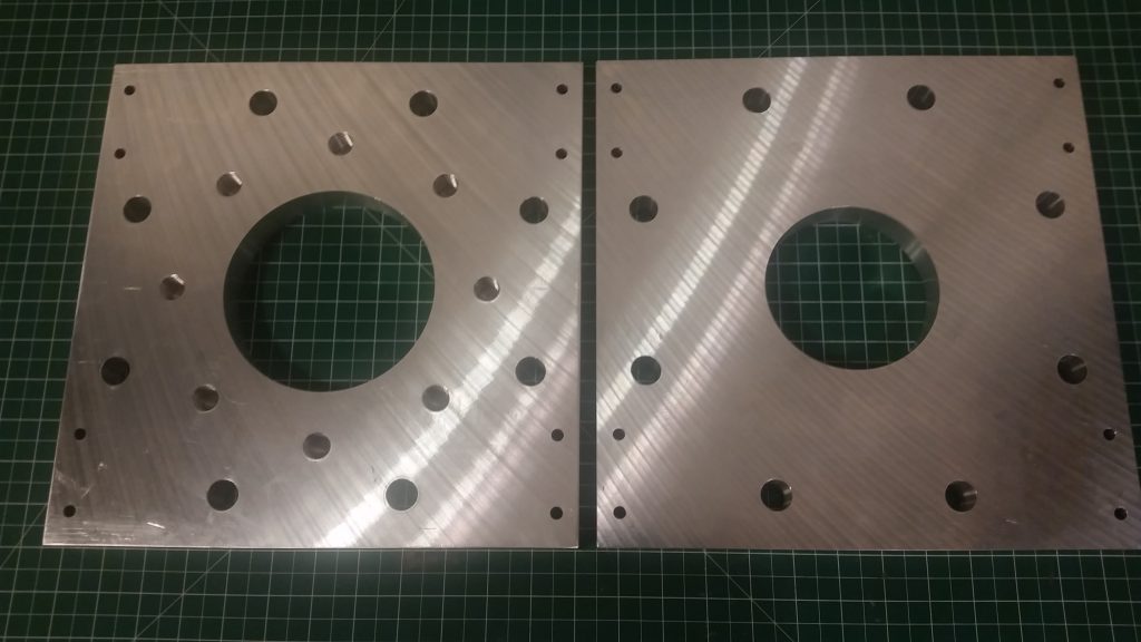
After a quick test fit, everything appeared to align. However, when looking to purchase the rest of the mounting hardware for the system, I discovered a potentially significant issue with my design. The plates required two sets of blind-tapped holes – one for the diffusion pump, and one for the 6″ conflat chamber. However, during the design and manufacturing of the plates, I specified these holes to be tapped with fine threads. Normally, fine threads are selected for high vacuum hardware, which is not normally an issue since the bolts, nuts, and tapped holes on the conflat flanges are made from stainless steel. I decided to just keep this standard with my design. I did not consider material selection of my plates. Being aluminum, proper machining practice dictates the use of coarse threads. Since aluminum is much softer than steel, the threads will already be weaker, and fine threads have a higher chance of stripping out. This would be devastating for my system – one stripped thread in the aluminum plate would potentially ruin the entire plate, requiring a new plate to be machined, which is currently not possible with the budget I have to work with. After doing calculations on shear strength of the threads for various materials, and talking with several of my mechanical engineering friends, I decided modifications to my design were required. I had several options to choose from, each with different pros and cons in terms of cost and risk. One would be using bolts of the same strength or lower strength than the plate material. This would mean aluminum bolts. However, since I may need to change out the chamber regularly, this would have high risk of continued wear and stress on the tapped holes, with no guarantee the bolts would shear first. The next option was to drill out the holes and use stainless steel Helicoil inserts. While this would greatly strengthen the threads of the holes, this required more machining and tapping, which still has the potential to go wrong. In addition, I may not be able to get the full thread engagement required, although Helicoil inserts can be stacked. Finally, the last option considered was using stud inserts instead of bolts. Studs are stronger than bolts, and reduces the shear forces on the tapped holes, since the entire bolt is no longer being torqued against the threads, but rather, the torque applied to the nut, directed to the stud, helping to decoupling the force seen on the tapped holes. I first considered using aluminum studs, however I discovered a second issue.
For the machining of the plates, I had also failed to specify the type of thread fit. Because of this, I found out that the larger tapped holes had a rather tight fit, while the holes for the conflat adapter were uncomfortably loose. Even with aluminum studs, the thread fit was so loose that it would still present a potential risk for stripping. After talking over the option with others, I decided the best route to pursue was to Loctite alloy steel studs into the threaded holes. In addition, anti-seize would be used on the nut side. In combination, this would practically eliminate any shear forces exerted on the tapped aluminum threads. For the steel inserts, hex-key set screws of appropriate length were selected, making it easy to insert the studs. Although Loctite red was used, making the assembly mostly permanent, the studs could still be removed if absolutely needed with some applied heat from a torch.
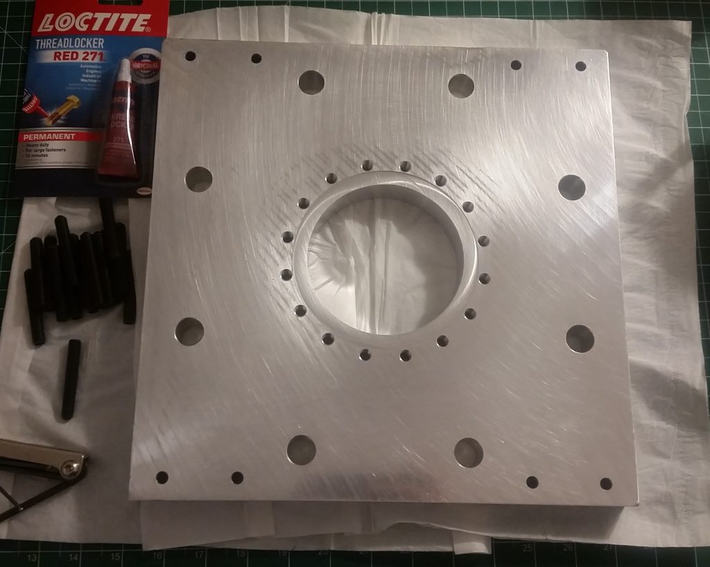
The new hardware was ordered, and the modification could be started. After degreasing the steel studs with several alcohol washes, as well as cleaning all of the tapped holes of any residual grease or particulates, the new studs could be Loctite in. As a word of advice from this experience, I found that 5/8-18 hardware is very limited, and was very difficult to locate proper setscrews for the studs. While I could use rod cut down to proper size, cutting out x8 studs of 5/8″ thick hardened steel or stainless would be quite an endeavor, and since the thread fittings were tight for these holes, driving them in would be a challenge without some sort of head to accept a tool to torque them in. However, I was able to find the studs I needed at Grainger – not cheap, but the least amount of risk.
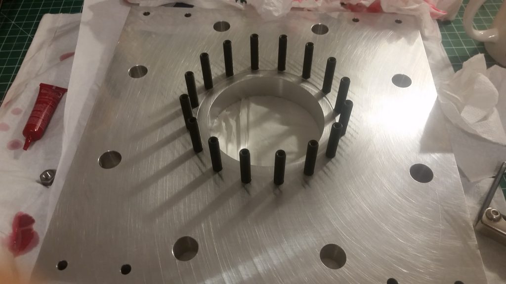
I decided to first work on the top plate with the smaller 5/16-24 inserts for the conflat adapter. Before permanently setting the studs, I decided to test fit each one into the holes, as well as test fit nuts along the full length, to make sure the studs I used had no defects in the threads. I applied an even coat along the 0.75″ length of engagement at the bottom, as well as a few beads up the sides of the blind tapped holes. Driving the studs tightly to the bottom seemed to lock them in place well with no play in the stud that I experienced earlier when test fitting everything. Any excess Loctite was wiped away from the plate, with care to prevent any from getting on the inset surface for the o-ring.
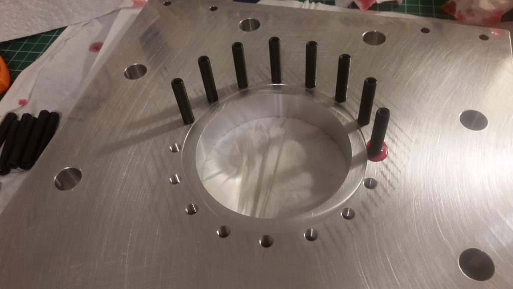
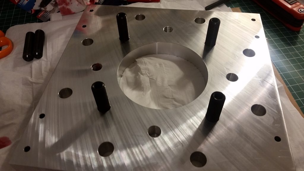
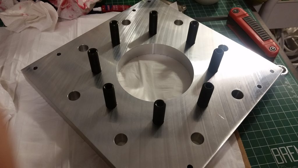
Atfter the top plate was complete, it was time to move on to the bottom plate with the larger 5/8″ bolts. For each bolt, like the previous plate, I decided to test fit every single stud to make sure the threads where clean, undamaged, and could be driven in smoothly. The tapped holes in the plates appeared to be fine, though I found a bolt or two that had less than optimal threads. Fortunately, I ordered a 10 pack, giving me 2 extra bolts. Loctite was again applied to the 0.75″ length of engagement, as well as a generous amount applied to the tapped threads and bottom of the hole. The studs were driven in tightly, and excess Loctite was wiped away. For the entire project, only two small tubes of Loctite was needed.

With both plates now modified, I could finally work towards the first preliminary assembly and test fitting of all the components of the high vacuum pumping stack, as well as do initial leak testing on the assembly with the roughing pump. Once this passed my initial set goal of 30 millitorr worst case, 20 millitorr best case, then the system would be ready for final assembly and high vacuum testing.
In the next blog segment, I will cover the initial preliminary pumping stack assembly and qualifying leak checks. After that, the real challenge begins in prepping the system for full high vacuum runs and mounting the final assembly to the test stand.