INITIAL HIGH VACUUM SYSTEM REQUIREMENTS
In this section of the walkthrough we will be going over the basic initial design objectives, parameters, requirements, and starting model of this high vacuum system. Before building any system, it is very important to have a clear set of goals, objectives, and initial parameters established. This will allow you to better and more efficiently design a solution that meets your exact needs and goals, and will help save a lot of time, money, and frustration in the long run. This also requires you to do extensive research into the system you are planning on designing and building, and knowing what is needed before hand. In this instance, a list of numerous projects were established for this vacuum system to operate with. This required significant research before hand to determine all subsystems required for each. This not only means the high vacuum chamber itself, but rough pumping, gas input, instrumentation, control, and system cooling, as well as power supplies for the various tests, including low and high voltage systems, ranging from DC to RF to pulsed. Below is a general list of the various modes of operation expected for this particular vacuum system, with the associated gas flow regimes (which will be briefly covered after):
1.) Pumpdown from atmosphere: 10^-2 Torr – 10^-7 Torr – molecular and transitional flows with water vapor loading
2.) Standard fusor operation without deuterium: 10^-2 Torr – transitional flow with air and water vapor loads
3.) Standard fusor operation with deuterium: 10^-2 Torr – transitional flow with deuterium
4.) Beam on Target and Beam Injected Fusor Systems for neutron production: <10^-4 Torr – molecular flow with deuterium
5.) Ion Beam systems with argon injection for non-neutron systems: <10^-4 Torr – molecular flow with argon
6.) Electron Gun Systems: <10^-6 Torr – molecular flow with water vapor loading
7.) Micro-thrusters: <10^-6 Torr – molecular flow with water vapor loading and argon
8.) Plasma Sources: <10^-3 Torr – molecular and transitional flows for deuterium, argon, and water vapor loading
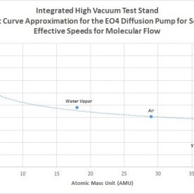
As a brief summary, molecular flow governs the flow of gases in high vacuum systems at pressures generally around 10^-4 Torr and lower. This is determined due to the fact that mean free path of molecules is large enough that molecules and residual gases interact with the walls of the system more than each other in the space between. Other factors can be used to calculate this region based on the system, which will be presented later. Transitional flow governs the flow of gases in a vacuum system in a region between molecular flow and roughing, usually between 10^-2 Torr and 10^-3 Torr. Due to the wide range of operating parameters, both regimes need to be calculated for this system, using the various gases present in the system. At vacuum levels from low vacuum to about 10^-7 Torr, the dominant gas load due to outgassing is water vapor. Since the system will not be operating yet in the ultra-high vacuum regime at levels of 10^-8 and lower, which is dominated by the outgassing of hydrogen sorbed in the metals, calculation in this area is not immediate. Since deuterium is already hydrogen, and the molecular masses are almost identical between the two, any calculations used for deuterium would be reasonable for hydrogen in the ultra-high vacuum regime for estimates as well.
The fundamental and most important relationship in high vacuum systems is determined in the equation S=Q/P, where S is the speed in L/s, Q is the gas load in Torr*L/s, and P is the pressure in Torr. By finding the effective speed of the system, ultimate pressure and gas loads for various process can be derived. Speed is determined by a large range of factors, including conductance, which is also a critical factor in high vacuum systems. Conductance itself is dependent on several factors, such as geometry, gas used, and temperature. For all processes calculated in this system, a temperature of 20C is assumed, which is the standard temperature used in literature for calculations and comparisons, usually using nitrogen or air.
The ultimate goal for these calculations can be boiled down into the following:
1.) Calculate the effective speed of the system for various gases based on processes used for molecular flow
2.) Calculate the effective speed of the system for various gases based on processes used for transitional flow (derived from molecular flow)
3.) Calculate the gas load due to outgassing (derived from materials and pumping conditions)
4.) Calculate the theoretical ultimate pressure of the system during pumpdown (derived from a and c)
5.) Calculate maximum allowable gas loads for various experiments (derived from a, c, and d)
6.) Calculate pumpdown times from atmosphere to rough vacuum
Due to the amount of calculations involved, initially only conductance and pumping speeds were determined for the initial design iterations. Once a final design layout was selected, the rest of the parameters could be calculated for that final design. Based on all of the above information, it will be reasonably known how the system should behave for each test setup, assuming the chamber and system is well prepared, sealed, and functioning prior to the experiment. Again these are very rough estimates in ideal scenarios, but should be agreeable with basic expectations for vacuum systems.
The current final version of the system is the result of numerous design iterations, based on a wide variety of parameters, including: costs and available funding, availability of components, experimental goals, CAD modelling, and initial calculations involving system conductances and effective speeds for various gases. The initial high vacuum system effort was based around a massive chamber. However, it was determined that it would be much more beneficial and safer to start as small as possible, get a solid system running, and then gradually increment up to larger systems. Because of this and other criteria, a topology was selected that is built around 2.75” Conflat hardware, which is ubiquitous and relatively cheap on eBay, which is the prime, number one best source for low cost scientific and high vacuum equipment out there. Despite its small size, 2.75″ CF hardware can be plenty of room for many types of systems as long as the equipment is appropriately sized and designed for the beam-pipe diameter. The systems that will be tested with this vacuum setup include: electron guns, ion guns, plasma sources, electric space propulsion, beam on target systems, and a fusor. The system therefore needs to be capable of supporting all of these experiments, while being modular and low cost to build. This requires not only being able to operate over a wide range of pressures, but also to utilize different gases, and have enough input ports for both adequate instrumentation as well as being able to accommodate future test setups.
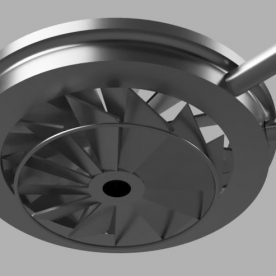
Prior to obtaining the hardware required for this build, an excellent high-throughput diffusion pump in brand new condition was obtained for free, which would serve as the backbone to the high vacuum pumping of the system. An outline of key requirements for the system is presented as follows:
1.) Low cost
2.) Small size, portable, and manageable to move
3.) Ability to operate from low to high vacuum, in the range of 10^-2 Torr to greater than 10^-7 Torr
4.) Modularity and expandability to support wide range of experiments
5.) Direct pumping line to maximize pump capability in a small system
6.) Input port for high vacuum pumping and roughing
7.) At least 2 input ports for a range of high vacuum gauges capable of reading from 10^-2 torr to greater than 10^-7 Torr
8.) At least 3 input ports for experimental setups
9.) Ability to support electron guns, ion guns, plasma sources, standard fusor, beam on target system, and potentially micro-thrusters, in addition to required feedback such as faraday cups, beam profiling, etc.
10.) At least one viewport for visual feedback
11.) Ability to both isolate and throttle the main chamber from the high vacuum pump
12.) Full system instrumentation, control, and monitoring for precise experimental setups and procedures
Before purchasing parts, the system was modeled with CAD software. Systems designed and developed at Applied Ion Systems currently use Fusion360, which is highly recommended to anyone – it is free, and has a massive range of capabilities and is incredibly powerful with a not-too-steep learning curve like some other CAD packages. In addition, it turns out that several online vendor such as Kurt J. Lesker and Ideal Vacuum provide a large selection of free CAD models for vacuum components.
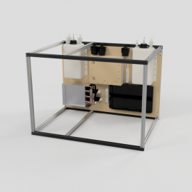
Below is a rendering of the initial V1 design of the small-scale multipurpose system:

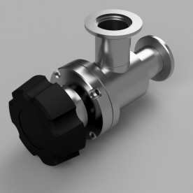
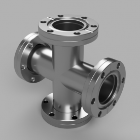
Initially this design incorporated a rather odd topology, utilizing a 90 degree manual valve from the diffusion pump to the pipeline. The valve is also useful as a throttle control for the diffusion pump depending on the process that is run. An adapter plate, made of 1″ aluminum, would be needed to go from the 5″ inlet of the diffusion pump to the 2.75″ CF flange on the valve. The pipeline further branches off to a 4-way 2.75” CF cross and KF25 cross to support instrumentation. The valve on the right is for roughing the system. Above the CF cross is the main chamber, consisting of a 2.75” 5-Way CF cross. The initial design was largely dictated by what was available on eBay. 90 degree valves are very cheap and easy to come by, and utilizing a mix of KF25 hardware with CF hardware could reduce the cost considering KF hardware is relatively inexpensive and easy to find. The 5-way cross was chosen due to its ability to support 3 inputs, as well as a viewport, and connection for pumping, and can be found at much lower prices than a 6-way cross, which would be preferable for functionality. The 4-way CF cross allows for connections to both high vacuum and roughing lines, which were initially separated for the system.
Although this could satisfy instrumentation and system input requirements, the setup seemed to be a bit awkward physically, and due to the pipeline and 90 degree bends in it, conductance and pumping speed would suffer. Since 2.75″ CF hardware already would have low limits in pumping speed in molecular flow, it was best to not further sacrifice system speed. The lower the speed, the less gas that can be supported for certain systems that require operation at lower vacuum levels. After weighing design trade-offs, the V1 design was scrapped in favor of further designs, which was also in part determined by the availability of new parts on eBay to improve the design. After many more hours of searching on eBay, some inline valves were located that made contributed to the system redesign. This will be detailed in the next section, along with the associated calculations for V2.