I. TESTING OVERVIEW
On May 5th, 2019, I attempted the first ignition test of the AIS-uPPT1 Micro Pulsed Plasma Thruster, after the prior day’s successful pumpdown and confirmation of the system at high vacuum. This was a big step forward in testing at Applied Ion Systems, and if successful, would be the start of future testing for open-source advanced electric propulsion for CubeSats. During the entire process, I also live-tweeted updates to the Applied Ion Twitter page, sharing details of the pumpdown, system operation, and ignition testing. As part of my research initiative into open-source electric propulsion, I feel that transparency is important and vital for development, and everything should be reported, both successes and failures. For each of my pumpdown and thruster tests, I also want to give others interested in this area an opportunity to witness and be a part of the testing phase of these advanced systems, and help make experimental electric propulsion more accessible to the community.
The vacuum system was well prepped from the previous day’s deep pumpdown to the mid-10^-6 Torr range. That morning before the test, the hydrogen thyratron trigger pulser and main capacitor bank charging supply was wired up and ready to go.
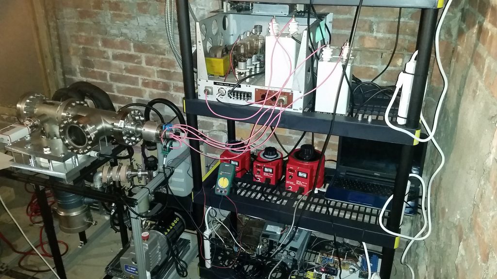
Pumpdown of the system was notably faster and improved. All systems were operating at nominal conditions, and the testing level of 10^-5 Torr was achieved quickly and without issue. Finally, it was time to turn on the high voltage supplies and attempt ignition.
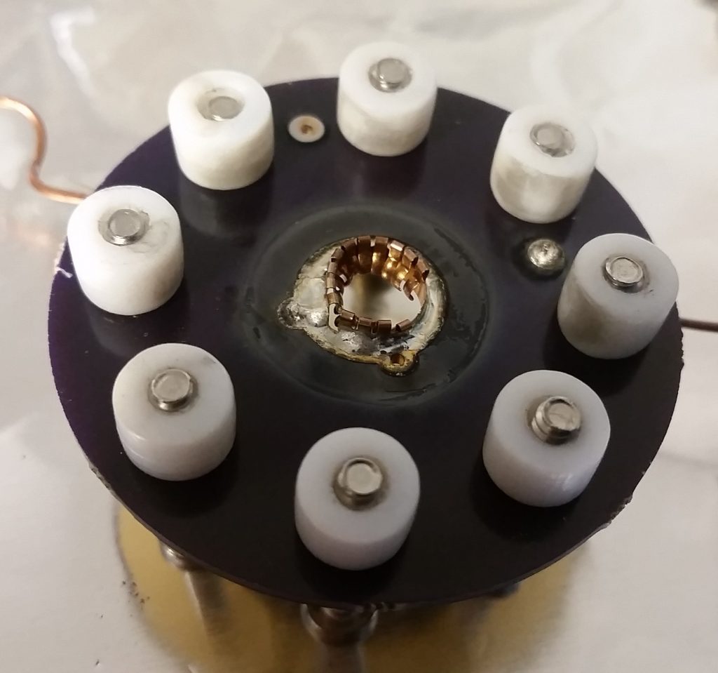
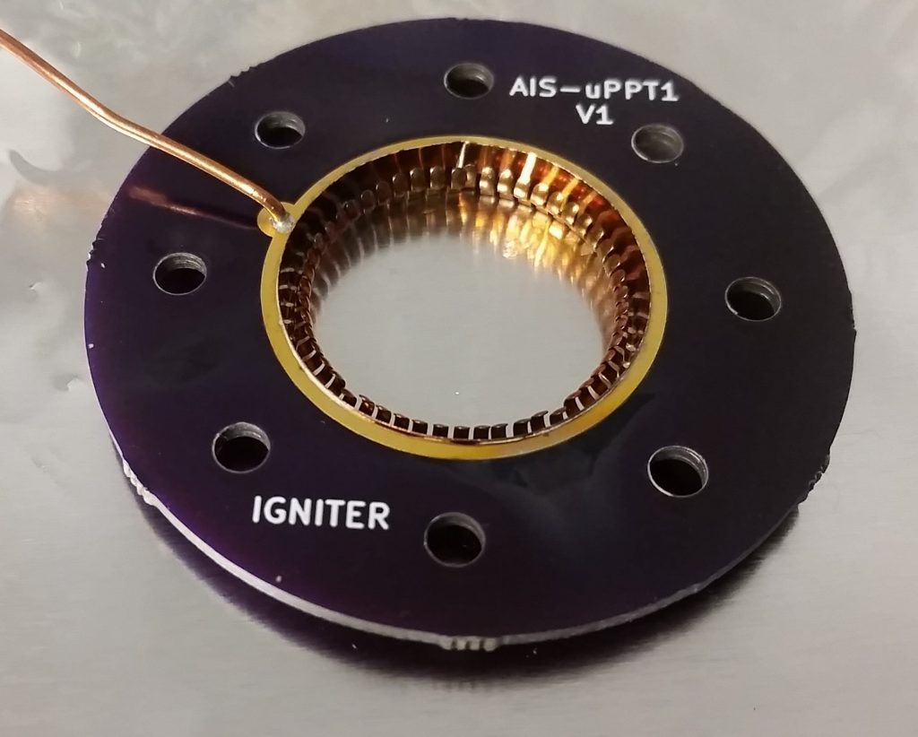
The main charging supply was set to around 1.2kV. The primary capacitor selected was a 3uF polypropylene film capacitor. The thyratron pulser was turned on, and the voltage slowly turned up, with the rep rate set to about 1 Hz. 1kv, 2kv, 3kv – the voltage climbed but still nothing. Turning up the voltage higher, I finally saw pulses of light coming from the thruster. However, very disappointingly, these pulses were not coming from the engine itself, but rather behind the first PCB board of the socket assembly. I immediately knew that the thruster assembly was suffering from improper breakdown, and most likely failing between the ignition board fingerstock connection, and the cathode board. Disappointed, but undeterred, I continued to adjust ignition and main bank voltages. For a few brief pulses, the main bank was ignited at higher voltage levels, but this occurred within the thruster socket still. The pulse of plasma exploded out radially from the socket, a beautiful sight to behold, but not where I needed it it form. Unfortunately, the first ignition test of this thruster had been a failure.
II. FAILURE ANALYSIS SUMMARY
During the testing phase, 2 potential modes of failure were identified – ignition arcing between the igniter board and cathode board, and main bank discharges at the rear of the entire thruster assembly. The thruster was de-mounted from the chamber to inspect issues closer.
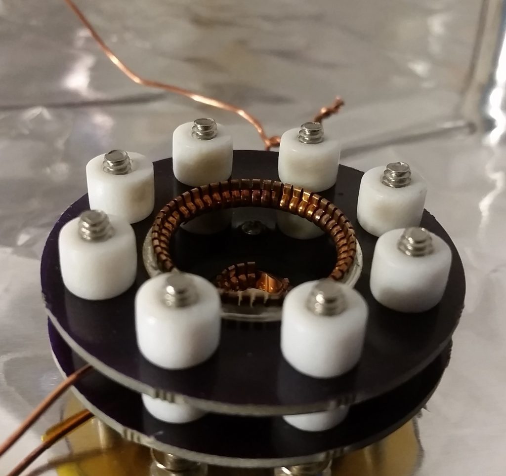
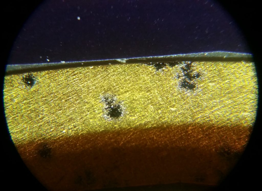
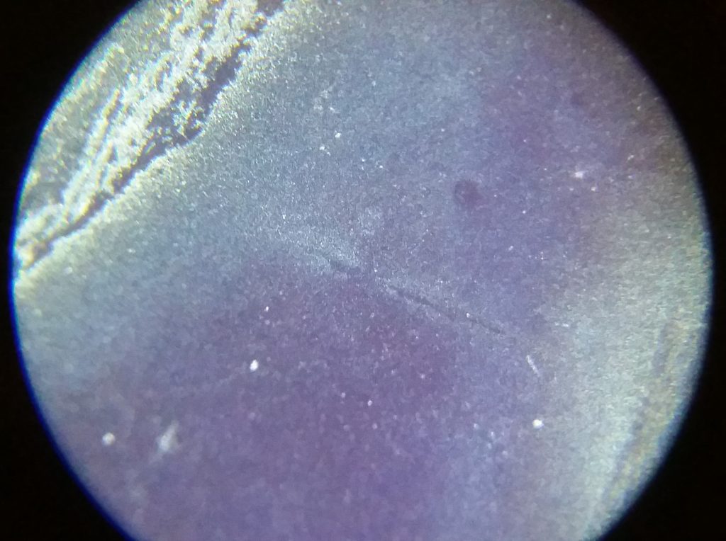
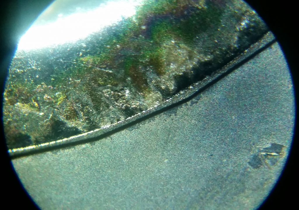
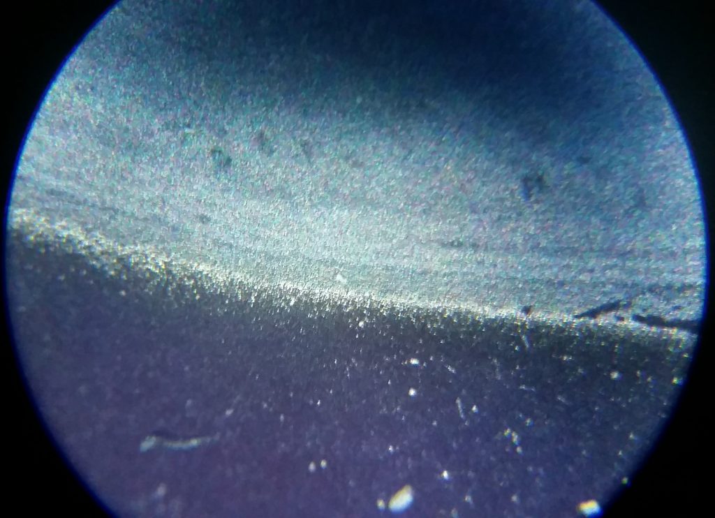
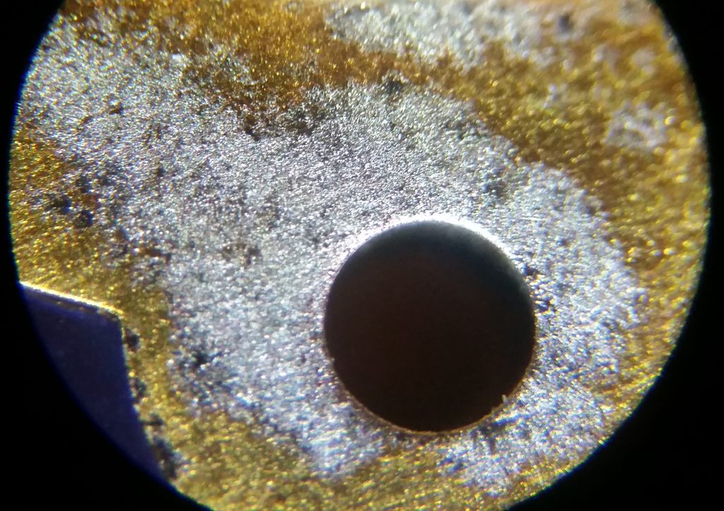
Inspection of the boards revealed evidence of arcing between the ignition board and the cathode board. This was in fact between the igniter socket fingerstock, and the cathode board surface traces. Ablation of the traces due to the ignition pulses can clearly be seen, and charring of the Teflon spacers between the igniter and cathode boards can be seen.
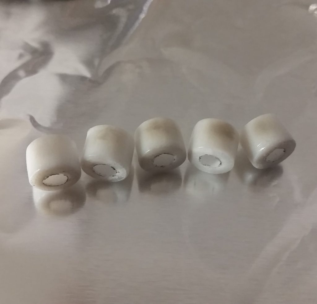
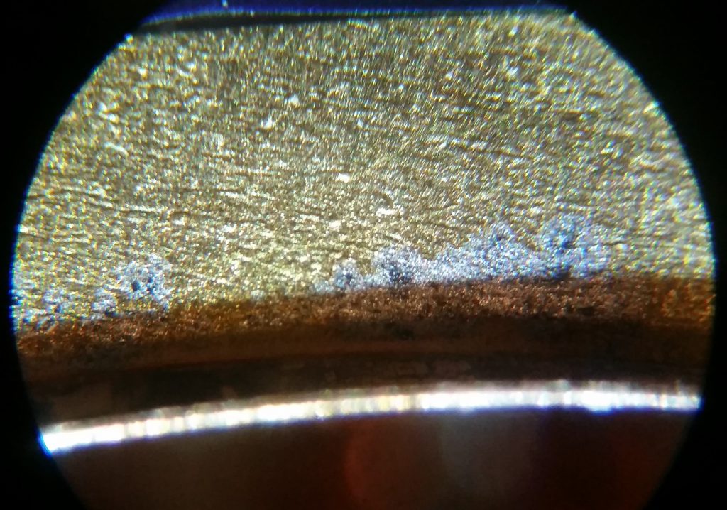
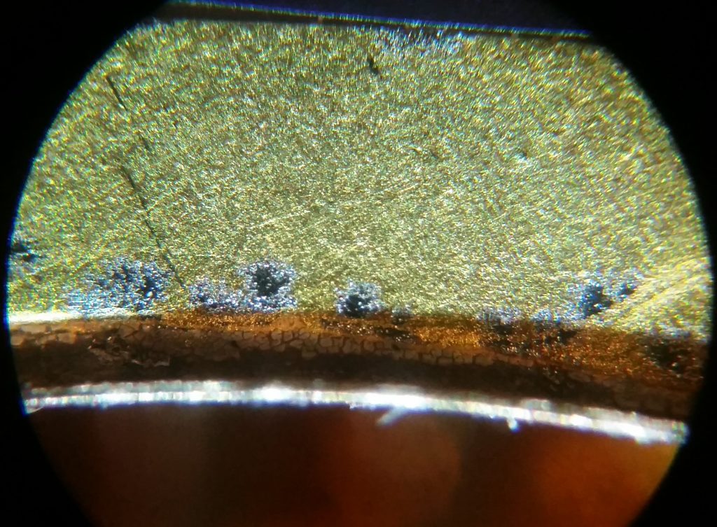
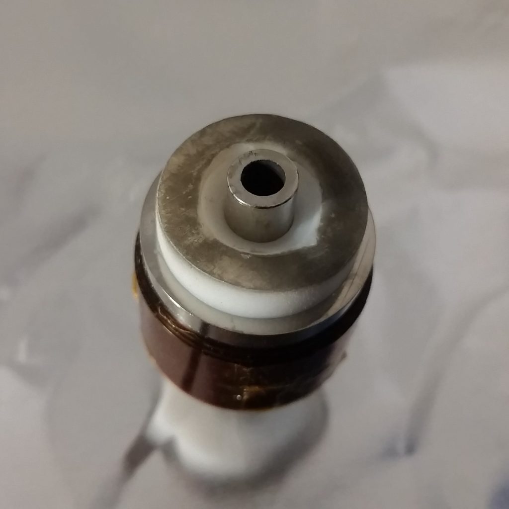
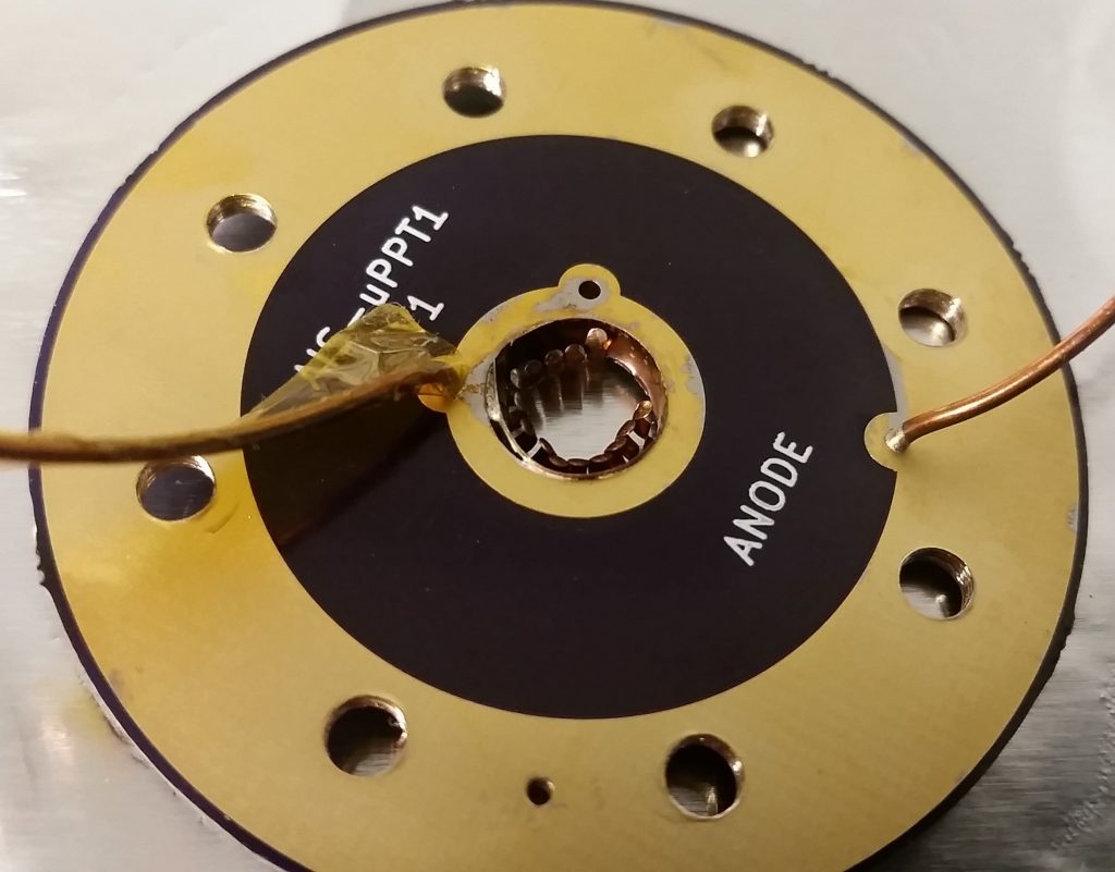
The second failure was immediately noticeable upon further disassembly of the PCB socket assembly. Charring of both the anode board as well as the back of the Teflon fuel bar was very visible, as well as evidence of arcing across the board. With further inspection, it was discovered that the Teflon fuel had ignited as an arc formed between the anode board central connection, and a side cathode wire connection hole. Due to the arcing of the igniter in the PCB socket assembly, local pressure was raised enough from ablation of the metal traces to initiate the main discharge. What is interesting to note is that despite the arcing occurring in only one location, very uniform ignition and ablation of the Teflon fuel was still observed.
III. TESTING AND FAILURE ANALYSIS REPORT
The full testing report and detailed failure analysis can be found below. This report includes all of the test parameters, testing procedure, observations, failure analysis with detailed pictures, and recommendations for future testing and iterations of the thruster. Although several arcing faults occurred in the PCB socket assembly, the primary cause of failure was the thruster design itself. The highly polished, smooth, and large surface area stainless steel electrodes ended up preventing the initiation of the ignition arc in the proper area at the given electrode spacing, and arcing eventually occurred externally in the socket at higher voltage levels, despite the fact that the cathode-igniter spacing was only 0.03″, while arcing in the socket occurred at distances of 0.1875″. While this highly anticipated test was unfortunately unsuccessful, it provided valuable insight to testing and failure modes of PPTs, and has been a great learning opportunity to improve the design.